RF-SABB (Wireless Signalling & Bell Box)
Hardware
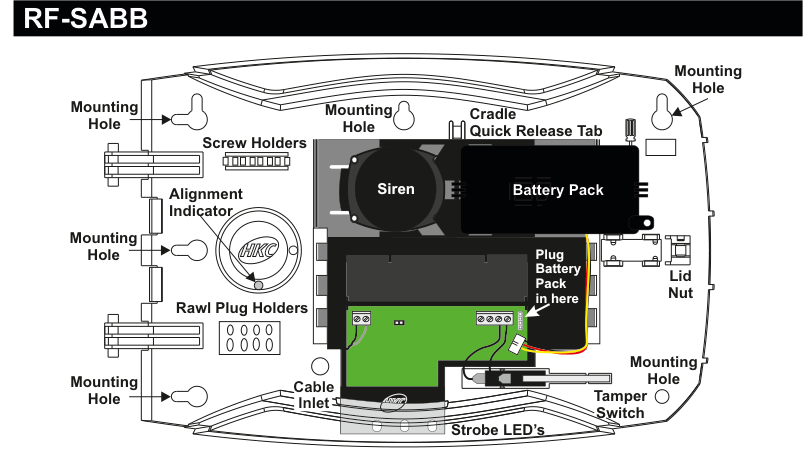
Internal view of the RF-SABB bell box with the lid removed. The device is oval-shaped. Left side (from top to bottom): Mounting Hole, Screw Holders (two horizontal holders), Alignment Indicator (circular HKC logo), Rawl Plug Holders (two horizontal holders), Mounting Hole, Cable Inlet. Centre: a large circular Siren speaker (top), a green PCB with connectors below it, and Strobe LED's along the bottom edge. Right side (from top to bottom): Mounting Hole, Cradle Quick Release Tab, Battery Pack (black rectangular module), connector area labelled Plug Battery Pack in here, Lid Nut, Mounting Hole, Tamper Switch. Additional Mounting Hole locations on the left and right edges of the case.
| Component | Description |
|---|---|
| Siren | Circular speaker (centre of unit) |
| Battery Pack | 6x CR123A 3V Lithium batteries (right side) |
| Strobe LED's | LED strip along bottom edge |
| Tamper Switch | Detects case opening (right side, below battery) |
| Cable Inlet | For wired power supply connection (bottom-left) |
| Cradle Quick Release Tab | Quick-release mechanism (top-right) |
| Mounting Holes | Six mounting points around the case perimeter |
| Screw Holders | Two holders on left side |
| Alignment Indicator | HKC logo circle for positioning (left side) |
| Rawl Plug Holders | Two holders below alignment indicator |
| Lid Nut | Secures lid to case (right side) |
Key Features
- Recommend that battery is changed every 3 years
-
400m Line-of-sight Radio Range
- Short-circuit J1 to test Strobe and J3 to test Siren
Add & ID on to the System

A three-column menu navigation flowchart. First column: 1 Service Menu / 2 Devices Menu (highlighted) / 3 Zone Menu. Arrow leads to second column: 1 RF Devices Menu (highlighted) / 2 Wired Devices Menu. Arrow leads to third column: 1 Add & ID RF Devices (highlighted) / 2 Locate RF Devices / 3 Remove RF Devices.
- To put an RF-SABB on to a SecureWave system go into engineer mode.
- Open the RF-SABB and plug in the battery pack to power it up.
- If you have a second device you can open it too at this stage and plug-in its battery pack.
- Don't close their lids just yet.
- Select the Devices Menu, then RF Devs Menu. Next select the Add & Id RF Devs option.
- Next, add and identify the device(s) as RF-SABB.
The sub-menu offers four device types:

A three-column sub-menu flowchart. First column: 1 Add & ID RF Devices (highlighted) / 2 Locate RF Devices / 3 Remove RF Devices. Arrow leads to second column: 1 Add&Id:RF Zones / 2 Add&Id:RF Keyfob / 3 Add&Id:RF Echo / 4 Add&Id:RF SABB (highlighted). Arrow from 4 Add&Id:RF SABB leads to Scanning RF Devs in the third column.
1 Add&Id:RF Zones— add and identify RF zone devices2 Add&Id:RF Keyfob— add and identify RF Keyfobs3 Add&Id:RF Echo— add and identify RF Echo sounders4 Add&Id:RF SABB— add and identify the RF-SABB
The system displays Devs Found - 000 when it starts scanning and as it finds its first device the display will change to Devs Found - 001. When the system has found all its devices, press PLAY/QUIT.
- Next, close the devices' tamper switches by fitting their lids.
- As you close the devices' tamper switches in sequence, you will hear an audible indication as each device is identified into the system.
The RF-Echo can have a delayed reaction.
RF Device Options (Programmable Settings)

A three-column navigation flowchart. First column: 1 Service Menu / 2 Devices Menu (highlighted) / 3 Zone Menu. Arrow to second column: 1 RF Devices Menu (highlighted) / 2 Wired Devices Menu. Arrow to third column: 1 Add & ID RF Devices / 2 Locate RF Devices / 3 Remove RF Devices / 4 RF Device Options (highlighted).
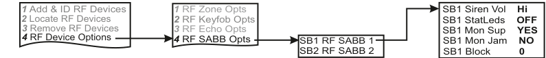
A four-column sub-menu flowchart. First column: 1 Add & ID RF Devices / 2 Locate RF Devices / 3 Remove RF Devices / 4 RF Device Options (highlighted). Arrow to second column: 1 RF Zone Opts / 2 RF Keyfob Opts / 3 RF Echo Opts / 4 RF SABB Opts (highlighted). Arrow to third column: SB1 RF SABB 1 / SB2 RF SABB 2. Arrow to fourth column showing default values: SB1 Siren Vol Hi / SB1 StatLeds OFF / SB1 Mon Sup YES / SB1 Mon Jam NO / SB1 Block 0.
The RF-SABB programmable options can be accessed as follows:
Menu navigation: 1 Service Menu → 2 Devices Menu → 1 RF Devices Menu → 4 RF Device Options
Go to the Devices Menu, then RF Devs Menu. Next select the RF Device Options.
From there go to RF SABB Opts and then select the RF-SABB number in question.
Sub-menu path: 4 RF Device Options → 4 RF SABB Opts → Select SABB (SB1, SB2, etc.)
StatLeds (Status LED's)
SB1 StatLeds (Status LED's) are defaulted to OFF to conserve battery energy. However, if you want to have them flash from left to right then select ALT by pressing YES or flash together in which case you select ON by pressing YES again.
| Setting | Description |
|---|---|
| OFF | LEDs disabled (default) |
| ALT | LEDs flash from left to right |
| ON | LEDs flash together |
Siren Vol (Siren Volume)
You can adjust the device's volume. SB1 Siren Vol (Siren Volume) can be set to LOW, MED or HI.
| Setting | Description |
|---|---|
| LOW | Low volume |
| MED | Medium volume |
| HI | High volume (default) |
Mon Sup (Monitored Supervisory)
SB1 Mon Sup (Monitored Supervisory signal) is defaulted to YES. When the device is "lost" for a prolonged period of time, a supervisory alarm is flagged by the panel. This can be turned off by selecting NO.
| Setting | Description |
|---|---|
| Mon Sup YES | Supervisory alarm enabled (default) |
| Mon Sup NO | Supervisory alarm disabled |
We recommend that this feature is left as YES.
Mon Jam (Monitor for Jamming)
SB1 Mon Jam (Monitor for Jamming), when set to YES, will trigger the siren for 15 minutes in the RF-SABB if there is a breakdown in the communications link with the panel and a jamming signal detected at 868MHz.
| Setting | Description |
|---|---|
| Mon Jam NO | Jamming detection disabled (default) |
| Mon Jam YES | Siren triggers for 15 min on jamming detection |
Block
SB1 Block 0 is where you can assign the device to a specific block (anywhere between 0 and 8).
| Setting | Description |
|---|---|
| Block 0 | Assigned to block 0 (default) |
| Block 0–8 | Assignable to any block from 0 to 8 |
Testing the RF-SABB
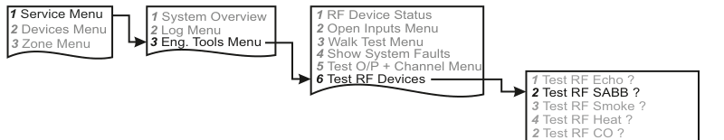
A four-column menu navigation flowchart. First column: 1 Service Menu (highlighted) / 2 Devices Menu / 3 Zone Menu. Arrow to second column: 1 System Overview / 2 Log Menu / 3 Eng. Tools Menu (highlighted). Arrow to third column: 1 RF Device Status / 2 Open Inputs Menu / 3 Walk Test Menu / 4 Show System Faults / 5 Test O/P + Channel Menu / 6 Test RF Devices (highlighted). Arrow to fourth column: 1 Test RF Echo ? / 2 Test RF SABB ? (highlighted) / 3 Test RF Smoke ? / 4 Test RF Heat ? / 2 Test RF CO ?.
Menu path: 1 Service Menu → 3 Eng. Tools Menu → 6 Test RF Devices → 2 Test RF SABB ?
Go to Test RF Devices (see menu map above) and select Test RF SABB ?. Select the RF-SABB you want to test and press REC/YES to activate and deactivate the siren and strobe.
Be aware that the siren test can be very loud.
Strobe and Siren Test (at the device)

Close-up view of the RF-SABB PCB (green circuit board) showing two test point jumpers. J1 (left) is labelled Strobe Test with + (left) and - (right) polarity markings. J3 (right) is labelled Bell Test. The HKC logo is visible on the board.
Alternatively you can test the RF-SABB's siren and strobe when you are physically at the device.
- To test the strobe, briefly short the two pins of J1 together.
- To test the siren, briefly short the two pins of J3 together.
Locate RF Devices
Menu path: 2 Devices Menu → 1 RF Devices Menu → 2 Locate RF Devices
Remove RF Devices
Menu path: 2 Devices Menu → 1 RF Devices Menu → 3 Remove RF Devices
Specifications
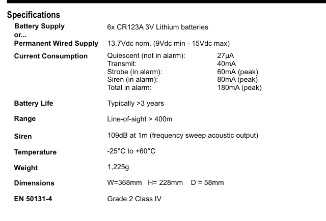
A two-column specifications table with parameter names in bold on the left and values on the right. Lists: Battery Supply — 6x CR123A 3V Lithium batteries; or Permanent Wired Supply — 13.7Vdc nom. (9Vdc min - 15Vdc max); Current Consumption — Quiescent (not in alarm): 27µA, Transmit: 40mA, Strobe (in alarm): 60mA (peak), Siren (in alarm): 80mA (peak), Total in alarm: 180mA (peak); Battery Life — Typically >3 years; Range — Line-of-sight > 400m; Siren — 109dB at 1m (frequency sweep acoustic output); Temperature — -25°C to +60°C; Weight — 1,225g; Dimensions — W=368mm H=228mm D=58mm; EN 50131-4 — Grade 2 Class IV.
| Parameter | Value |
|---|---|
| Battery Supply | 6x CR123A 3V Lithium batteries |
| or Permanent Wired Supply | 13.7Vdc nom. (9Vdc min - 15Vdc max) |
| Current Consumption | Quiescent (not in alarm): 27µA / Transmit: 40mA / Strobe (in alarm): 60mA (peak) / Siren (in alarm): 80mA (peak) / Total in alarm: 180mA (peak) |
| Battery Life | Typically >3 years |
| Range | Line-of-sight > 400m |
| Siren | 109dB at 1m (frequency sweep acoustic output) |
| Temperature | -25°C to +60°C |
| Weight | 1,225g |
| Dimensions | W=368mm H=228mm D=58mm |
| EN 50131-4 | Grade 2 Class IV |
If StatLeds (shorthand for Status LEDs) are enabled the batteries will need to be replaced every 6 to 8 months. We recommend that if you would like to use this feature that a secondary battery pack is installed (part number: BAT-PKRFSB6V). Alternatively wire 12Vdc to the SABB and remove the battery pack and install a 6V NiMH rechargeable battery pack (part number: BAT-8.4).