RF-PIR-DT (Wireless Dual Technology PIR)
Hardware
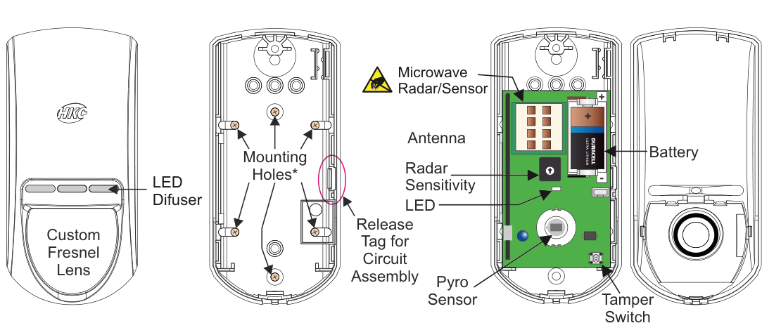
Four views of the RF-PIR-DT device. Front view (far left): a rounded rectangular unit with an LED Diffuser window and a large Custom Fresnel Lens covering the lower portion. Rear case (second from left): shows Mounting Holes (marked with asterisk) and a Release Tag for Circuit Assembly. Internal view (second from right): the circuit board showing a Microwave Radar/Sensor module (top, with warning icon), Antenna, Radar Sensitivity adjustment potentiometer, LED, Pyro Sensor, and the Release Tag for Circuit Assembly. Rear case with battery (far right): shows a single Battery compartment (Duracell Ultra Lithium) and a Tamper Switch.
| Component | Description |
|---|---|
| LED Diffuser | Front window for status LED visibility |
| Custom Fresnel Lens | PIR detection lens (lower front face) |
| Mounting Holes | For wall mounting (rear case, marked with asterisk) |
| Release Tag | Pull tag for circuit board assembly removal |
| Microwave Radar/Sensor | Microwave radar module (top of circuit board, warning icon) |
| Antenna | RF communication antenna (on circuit board) |
| Radar Sensitivity | Adjustable potentiometer for radar detection range (on circuit board) |
| LED | Status indicator (on circuit board) |
| Pyro Sensor | Passive infrared detection element (on circuit board) |
| Battery | Duracell Ultra Lithium, 3Vdc, 1400mAh |
| Tamper Switch | Detects case opening (rear case) |
Key Features
- 15m Pyro Detection
- 15m Radar Detection
- Very Low Current Consumption
- Long Battery Life (typically up to 3 years)
- >400m Line-of-sight Radio Range
- Close-in Detection
- Adjustable Sensitivity
- Noise Immunity using Digital Filtering
- Temperature Compensation
Add & ID on to the System

A three-column menu navigation flowchart. First column: 1 Service Menu / 2 Devices Menu / 3 Zone Menu. Arrow leads to second column: 1 RF Devices Menu / 2 Wired Devices Menu. A warning icon with red text states: "RF-PIR-DT can connect to RF-Expander". Arrow leads to third column: 1 Add & ID RF Devices / 2 Locate RF Devices / 3 Remove RF Devices.
RF-PIR-DT can connect to RF-Expander.
- To put an RF-PIR-DT on to a SecureWave system go into engineer mode. Select the Devices Menu, then RF Devs Menu. Next, select the Add & Id RF Devs option.
- Now you have a choice to add and identify the RF-PIR-DT and map it onto either a zone or point location.
To conserve zones it would be best to add and ID your RF-PIR-DTs onto Points (of which there are 40) first before you assign them to Zones.
The sub-menu offers two device types:

A three-column sub-menu flowchart. First column: 1 Add & ID RF Devices / 2 Locate RF Devices / 3 Remove RF Devices. Arrow leads to second column: 1 Add&Id:RF Zones / 2 Add&Id:RF Points. Each option has an arrow leading to Scanning RF Devs in the third column.
1 Add&Id: RF Zones— add and identify the RF-PIR-DT as a zone device2 Add&Id: RF Points— add and identify the RF-PIR-DT as a point device
The system displays Devs Found - 000 when it starts scanning and as it finds its first device the display will change to Devs Found - 001. When the system has found all its devices you will be prompted to close the devices' tamper switches.
A full scan will take about a minute and may be halted at any time by pressing QUIT.
Close the devices' tamper switches in sequence. You will hear an audible indication as each device is identified into the system.
The RF-Echo can have a delayed reaction.
RF Device Options (Programmable Settings)

A three-column navigation flowchart. First column: 1 Service Menu / 2 Devices Menu / 3 Zone Menu. Arrow to second column: 1 RF Devices Menu / 2 Wired Devices Menu. Arrow to third column: 1 Add & ID RF Devices / 2 Locate RF Devices / 3 Remove RF Devices / 4 RF Devs Options (highlighted).

A three-column sub-menu flowchart. First column: 1 Add & ID RF Devices / 2 Locate RF Devices / 3 Remove RF Devices / 4 RF Devs Options. Arrow to second column: 1 RF Zone Opts / 2 RF Point Opts. Arrow to third column showing default values: 1 Settings — MED / 2 Mon Sup — YES.
The RF-PIR-DT's programmable options can be accessed as follows:
Menu navigation: 1 Service Menu → 2 Devices Menu → 1 RF Devices Menu → 4 RF Devs Options
To get to either the RF-Zones or RF-Points options menu; select the Devices Menu. Then RF Devs Menu. Next select the RF Devs Options.
From there go to either the RF Zone Opts or RF Point Opts menu and then select the RF-PIR-DT number in question.
Sensitivity (Settings)
You can now select the sensitivity of the RF-PIR-DT. The three levels are LOW, MED and HI.
| Setting | Value |
|---|---|
| LOW | Low sensitivity |
| MED | Medium sensitivity (default) |
| HI | High sensitivity |
The Radar sensitivity is only adjustable by twisting the on-board potentiometer.
The unit only flags an activation when the system is armed and when both PIR and Radar circuits are simultaneously triggered.
Monitored Supervisory (Mon Sup)
Another option is Mon Sup (Monitored Supervisory signal) is defaulted to YES. When the device is "lost" for >120 minutes, a supervisory alarm is flagged by the panel. This can be turned off by selecting NO. However, we recommend that this feature is left as YES.
We recommend that this feature is left as YES.
Locate RF Devices

A three-column menu navigation flowchart. First column: 1 RF Devices Menu / 2 Wired Devices Menu. Arrow to second column: 1 Add & ID RF Devices / 2 Locate RF Devices (highlighted) / 3 Remove RF Devices. Arrow to third column: 1 Locate:RF Zones / 2 Locate:RF Points.
To locate an RF-PIR-DT go to the Devices Menu in engineer mode and follow the menu path below.
Menu path: 2 Devices Menu → 1 RF Devices Menu → 2 Locate RF Devices
Then select:
1 Locate: RF Zones→ select zone number2 Locate: RF Points→ select point number
In the Locate: RF Zones or Locate: RF Points you will observe the following:
PIR located — LED turns on/off every second.
- You will automatically be brought to either zone 1 or the first point (P50).
- When you want to move on to the next zone or point then press # (next).
Remove RF Devices

A three-column menu navigation flowchart. First column: 1 RF Devices Menu / 2 Wired Devices Menu. Arrow to second column: 1 Add & ID RF Devices / 2 Locate RF Devices / 3 Remove RF Devices (highlighted). Arrow to third column: 1 Remove:RF Zones / 2 Remove:RF Points.
Menu path: 2 Devices Menu → 1 RF Devices Menu → 3 Remove RF Devices
Then select:
-
1 Remove: RF Zones→ select zone number -
2 Remove: RF Points→ select point number -
To remove an RF-PIR-DT go to the Devices Menu in engineer mode and follow the menu path above.
-
You will automatically be brought to either zone 1 or the first point (P50).
-
Go to the zone or point you want to remove and press REC/YES.
Range of Detection
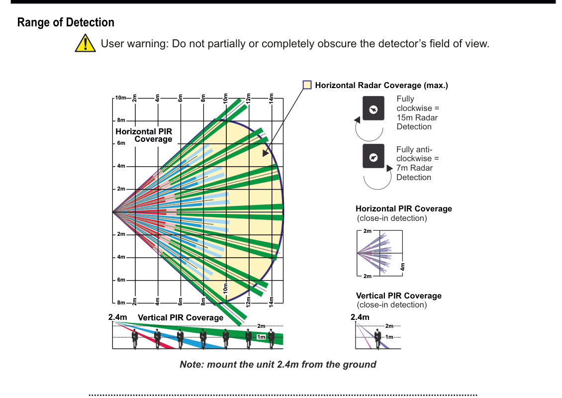
"Range of Detection" heading with a warning icon: "User warning: Do not partially or completely obscure the detector's field of view."
Five coverage diagrams and a potentiometer reference are shown:
-
Horizontal PIR Coverage (top-down view, left): A large fan-shaped detection pattern with multiple coloured beams (blue, red, green, magenta) radiating outward. Distance markers at 2m, 4m, 6m, 8m, 10m, 12m, and 14m intervals along the forward axis.
-
Horizontal Radar Coverage (max.) (top-down view, overlaid): A rectangular coverage zone shown as a white/yellow overlay on the PIR coverage diagram, extending outward from the sensor.
-
Horizontal PIR Coverage (close-in detection) (top-down view, right): A smaller concentrated detection pattern extending approximately 2m in front of the sensor.
-
Vertical PIR Coverage (side view, bottom-left): Mounted at 2.4m height, beams angle downward from the sensor to the floor. Distance markers along the floor at 2m intervals reaching 14m.
-
Vertical PIR Coverage (close-in detection) (side view, bottom-right): Mounted at 2.4m height, short-range beams covering approximately 1m–2m directly below the sensor.
Radar sensitivity potentiometer reference (top-right): Two potentiometer diagrams showing: "Fully clockwise = 15m Radar Detection" and "Fully anti-clockwise = 7m Radar Detection".
"Note: mount the unit 2.4m from the ground" appears at bottom centre.
User warning: Do not partially or completely obscure the detector's field of view.
Horizontal PIR Coverage (top-down view):
- Main detection: fan-shaped pattern with multiple coloured beams extending to 14m, with coverage zones at 2m, 4m, 6m, 8m, 10m, 12m, and 14m
- Close-in detection: concentrated coverage within approximately 2m × 4m directly in front of the sensor
Horizontal Radar Coverage (max.):
- Rectangular coverage zone overlaid on the PIR pattern
- Range adjustable via the on-board potentiometer:
- Fully clockwise = 15m Radar Detection
- Fully anti-clockwise = 7m Radar Detection
Vertical PIR Coverage (side view, mounted at 2.4m):
- Main detection: beams angle downward from 2.4m mounting height to floor level, reaching out to 14m horizontally with markers at 2m intervals
- Close-in detection: short-range beams covering 1m–2m below the sensor
Mount the unit 2.4m from the ground.
Specifications
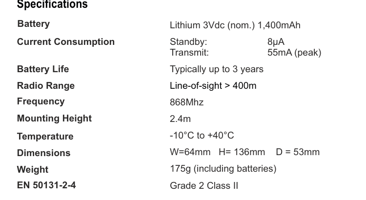
A two-column specifications table with parameter names in bold on the left and values on the right. Lists: Battery — Lithium 3Vdc (nom.) 1,400mAh; Current Consumption — Standby: 8µA, Transmit: 55mA (peak); Battery Life — Typically up to 3 years; Radio Range — Line-of-sight > 400m; Frequency — 868Mhz; Mounting Height — 2.4m; Temperature — -10°C to +40°C; Dimensions — W=64mm H=136mm D=53mm; Weight — 175g (including batteries); EN 50131-2-4 — Grade 2 Class II.
| Parameter | Value |
|---|---|
| Battery | Lithium 3Vdc (nom.) 1,400mAh |
| Current Consumption | Standby: 8µA / Transmit: 55mA (peak) |
| Battery Life | Typically up to 3 years |
| Radio Range | Line-of-sight > 400m |
| Frequency | 868MHz |
| Mounting Height | 2.4m |
| Temperature | -10°C to +40°C |
| Dimensions | W=64mm H=136mm D=53mm |
| Weight | 175g (including batteries) |
| EN 50131-2-4 | Grade 2 Class II |