Menu Navigation - Using Menu Keys
Key-in 4567 to access the Engineer Mode. This will need to be validated with a User Code. To do this, key-in a valid User Code i.e. 1111 (or 1234 in the UK). You are now in the Service Menu.
This section illustrates how to move around the menu structure in the SW-10270 control panel. There are five menu keys used for menu navigation. The following diagram describes their functions.
Menu Keys
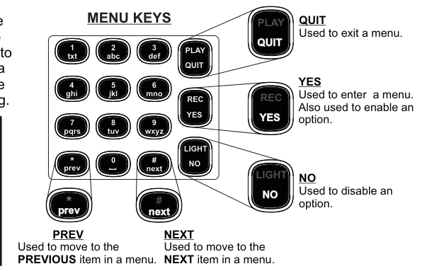
Photo of the SW-10270 Remote Keypad with menu key callout labels. The keypad has a 4x4 grid of numeric keys (1-9, 0, *, #) plus four function keys (PLAY/QUIT, REC/YES, LIGHT/NO). Five menu navigation keys are highlighted with callout boxes:
- QUIT (PLAY/QUIT key, top-right): Used to exit a menu.
- YES (REC/YES key, middle-right): Used to enter a menu. Also used to enable an option.
- NO (LIGHT/NO key, bottom-right): Used to disable an option.
- NEXT (# key, bottom-right of number pad): Used to move to the NEXT item in a menu.
- PREV (* key, bottom-left of number pad): Used to move to the PREVIOUS item in a menu.
The numeric keys are labeled with their text characters: 1/txt, 2/abc, 3/def, 4/ghi, 5/jkl, 6/mno, 7/pqrs, 8/tuv, 9/wxyz, 0/space.
| Key | Function |
|---|---|
| QUIT (PLAY/QUIT) | Used to exit a menu |
| YES (REC/YES) | Used to enter a menu. Also used to enable an option |
| NO (LIGHT/NO) | Used to disable an option |
| NEXT (# key) | Used to move to the next item in a menu |
| PREV (* key) | Used to move to the previous item in a menu |
When typing in zone descriptions etc., the cursor will move on to the next letter after a short period — just like mobile phone texting.
Keypad Character Set
| Key | Characters |
|---|---|
| 1 | 1 $ · ! % & * ( ) |
| 2 | a b c A B C 2 + = |
| 3 | d e f D E F 3 ; ? |
| 4 | g h i G H I 4 < > |
| 5 | j k l J K L 5 ` / |
| 6 | m n o M N O 6 - = |
| 7 | p q r s P Q R S 7 |
| 8 | t u v T U V 8 + = |
| 9 | w x y z W X Y Z 9 |
| 0 | space . , ' : - 0 @ # |
The next two pages contain the main areas of the programming menu.
Programming Menu Tree
Menus 1–6
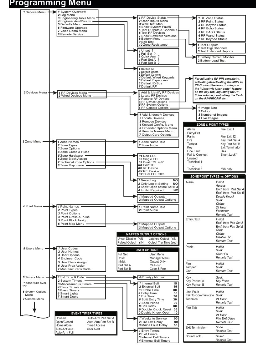
Large tree diagram showing the complete programming menu structure for menus 1–6 of the SW-10270 panel. The hierarchy flows left-to-right with green numbered boxes on the left connecting via lines to sub-menus extending rightward.
1 Service Menu expands to: 1 System Overview, 2 Log Menu, 3 Engineering Tools Menu (with sub-items: 1 Test Outputs, 2 Open Inputs Menu, 3 Walk Test Menu, 4 Show System Faults, 5 Test Outputs & Channels, 6 Test RF Devices with RF Device Status, 7 Show Software Versions, 8 Battery Menu, 9 Bell Test, 10 Zone Resistance), 4 Engineer Arm/Disarm, 5 Defaults Menu (7 default types), 6 Firmware Upgrade, 7 Voice Demo Menu, 8 Remote Service.
2 Devices Menu splits into: 1 RF Devices Menu (6 sub-items including Camera Options) and 2 Wired Devices Menu (7 sub-items).
3 Zone Menu has 8 sub-items including Zone Names, Zone Types, Zone Options, Zone Gross & Pulse, Zone Hardware, Zone Block Assign, Technical Zone Options, Zone Map Menu.
4 Point Menu has 6 sub-items mirroring Zone Menu.
5 Users Menu has 7 items: User Codes, User Names, User Options, Engineer Code, User Block Assign, User Prox Assign, Manufacturer's Code.
6 Timers Menu shows: Set Time & Date, System Timers (10 timer values), Miscellaneous Timers, Block Timers, Event Timers, Smart Lights, Smart Doors.
Reference panels on the right side show: Zone Hardware types, Zone & Point Types list, Zone/Point Types vs Options matrix, User Options list, Event Timer Types, and Mapped Output Options.
1 Service Menu
- 1 System Overview
- 2 Log Menu
- 3 Engineering Tools Menu
- 1 Test Outputs
- 2 Open Inputs Menu
- 3 Walk Test Menu
- 4 Show System Faults
- 5 Test Outputs & Channels — 1 Test Outputs, 2 Test Digi Channels, 3 Test Extended Reports
- 6 Test RF Devices
- RF Device Status: 1 RF Zone Status, 2 RF Point Status, 3 RF Keyfob Status, 4 RF Echo Status, 5 RF SABB Status, 6 RF Wand Status, 7 RF Keypad Status
- 7 Show Software Versions
- 8 Battery Menu — 1 Battery Current Monitor, 2 Battery Load Test
- 9 Bell Test
- 10 Zone Resistance
- 4 Engineer Arm/Disarm — 1 Unset, 2 Full Set, 3 Quick Arm, 4 Part Set A, 5 Part Set B
- 5 Defaults Menu
- 1 Default All
- 2 Default Users
- 3 Default Comms
- 4 Default Wired Keypads
- 5 Default Expanders
- 6 Default ID Bus
- 7 Default RF
- 6 Firmware Upgrade
- 7 Voice Demo Menu
- 8 Remote Service
2 Devices Menu
- 1 RF Devices Menu
- 1 Add & Identify RF Devices
- 2 Locate RF Devices
- 3 Remove RF Devices
- 4 RF Device Options — for adjusting RF-PIR sensitivity, activating/deactivating the magnetic contacts in RF-Contact/Sensors, turning on the "Unset via User-code" feature on the key-fob, adjusting the RF-Echo volume, controlling the flash on the RF-PIRCAM, etc.
- 5 RF System Options
- 6 RF Camera Options — 1 Image Size, 2 Colour, 3 Number of Images, 4 Live Images
- 2 Wired Devices Menu
- 1 Add & Identify Devices
- 2 Locate Devices
- 3 Remove Devices
- 4 Keypad Config. Menu
- 5 Expander Options Menu
- 6 Remote Names Menu
- 7 Output Card Options
3 Zone Menu
- 1 Zone Names — 1 Zone Name Text, 2 Zone Audio
- 2 Zone Types
- 3 Zone Options
- 4 Zone Gross & Pulse
- 5 Zone Hardware
- 6 Zone Block Assign
- 7 Technical Zone Options — 1 Never Log (NO), 2 Only Log at Setting (NO), 3 Show Open before Set (NO), 4 Inhibit Required (NO)
- 8 Zone Map Menu — 1 Mapped Outputs, 2 Mapped Output Options
4 Point Menu
- 1 Point Names — 1 Point Name Text, 2 Point Audio
- 2 Point Types
- 3 Point Options
- 4 Point Gross & Pulse
- 5 Point Block Assign
- 6 Point Map Menu — 1 Mapped Outputs, 2 Mapped Output Options
5 Users Menu
- 1 User Codes
- 2 User Names
- 3 User Options
- 4 Engineer Code
- 5 User Block Assign
- 6 User Prox Assign
- 7 Manufacturer's Code
6 Timers Menu
- 1 Set Time & Date (dd/mm/yy hh:mm)
- 2 System Timers
- 1 Internal Bell (15 mins)
- 2 External Bell (15 mins)
- 3 Strobe Time (00)
- 4 Entry Time (30 secs)
- 5 Exit Time (30 secs)
- 6 Split Entry Time (30 secs)
- 7 Soak Period (00)
- 8 Bell Delay (00)
- 9 Double Knock Reset (05)
- 0 Double Knock Open (10)
- 3 Miscellaneous Timers — 1 Weeks to Service (00), 2 Fire Exit Delay (00), 3 Mains Fault Delay (55)
- 4 Block Timers — 1 Entry Timers, 2 Exit Timers, 3 Internal Bell Timers, 4 External Bell Timers
- 5 Event Timers
- 6 Smart Lights
- 7 Smart Doors
Menus 7–9
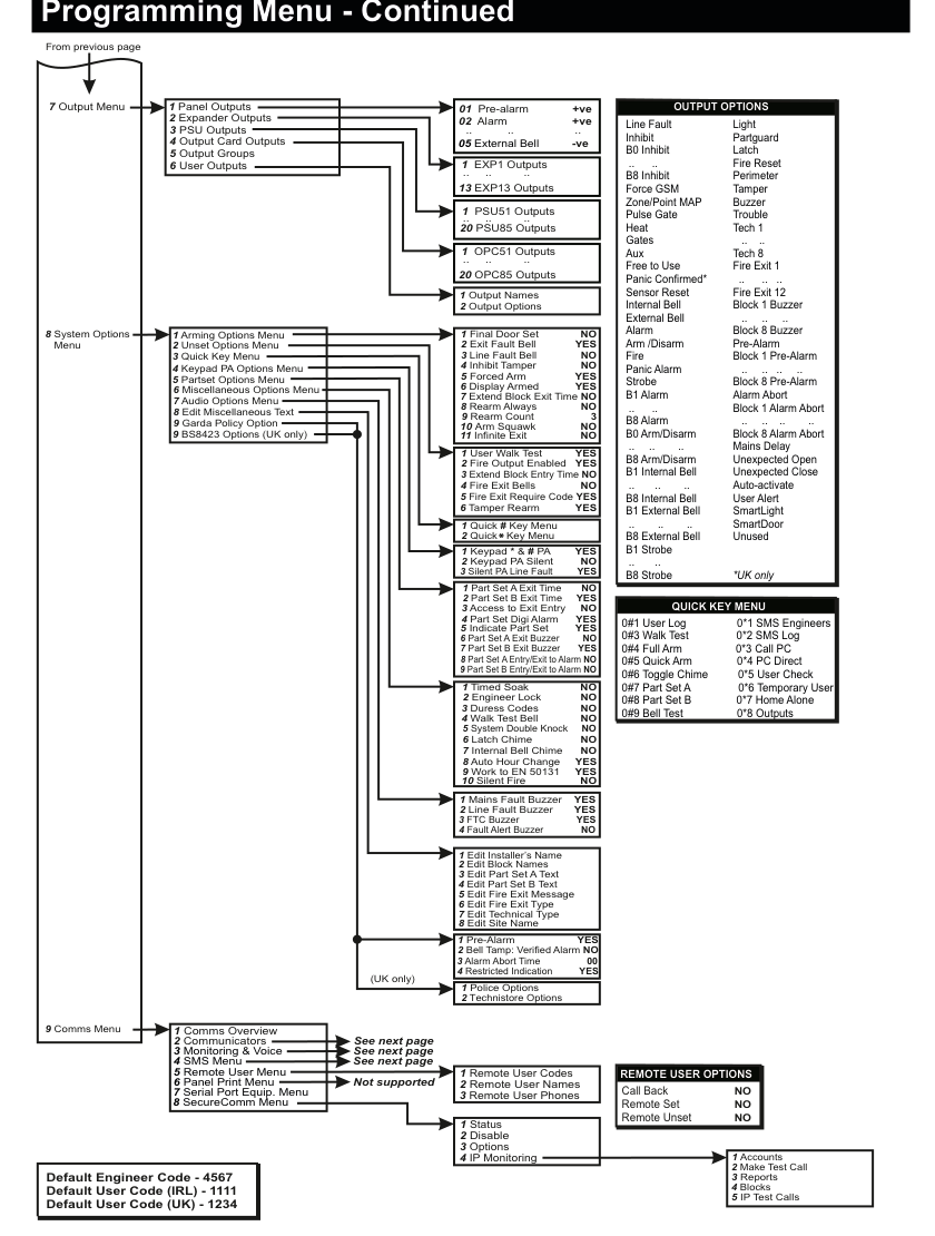
Continuation of the programming menu tree diagram showing menus 7–9.
7 Output Menu has 6 sub-items: 1 Panel Outputs (01–05), 2 Expander Outputs (EXP1–EXP13), 3 PSU Outputs (PSU51–PSU85), 4 Output Card Outputs (OPC51–OPC85), 5 Output Groups, 6 User Outputs. Each output has Output Names and Output Options sub-menus.
8 System Options Menu is the largest section with 9 sub-menus: 1 Arming Options (11 settings), 2 Unset Options (6 settings), 3 Quick Key Menu, 4 Keypad PA Options (3 settings), 5 Partset Options (9 settings), 6 Miscellaneous Options (10 settings), 7 Audio Options (4 settings), 8 Edit Miscellaneous Text (8 items), 9 Garda Policy / BS8423 Options.
Reference panels on the right show: the large Output Options list (60+ output types), the Quick Key Menu shortcuts (0#1 through 0#9 and 0*1 through 0*8), and Remote User Options defaults.
9 Comms Menu begins at the bottom-left with sub-items continuing on the next page.
7 Output Menu
- 1 Panel Outputs (01 +ve, 02 +ve, 03 −ve, 04 −ve, 05 External Bell) — each with: 1 Output Names, 2 Output Options
- 2 Expander Outputs (EXP1–EXP13) — each with: 1 Output Names, 2 Output Options
- 3 PSU Outputs (PSU51–PSU85, up to 20 each) — each with: 1 Output Names, 2 Output Options
- 4 Output Card Outputs (OPC51–OPC85, up to 20 each) — each with: 1 Output Names, 2 Output Options
- 5 Output Groups
- 6 User Outputs
8 System Options Menu
- 1 Arming Options Menu
- 1 Final Door Set (NO)
- 2 Exit Fault Bell (YES)
- 3 Line Fault Bell (NO)
- 4 Inhibit Tamper (NO)
- 5 Forced Arm (YES)
- 6 Display Armed (YES)
- 7 Extend Block Exit Time (NO)
- 8 Rearm Always (NO)
- 9 Rearm Count (3)
- 10 Arm Squawk (NO)
- 11 Infinite Exit (NO)
- 2 Unset Options Menu
- 1 User Walk Test (YES)
- 2 Fire Output Enabled (YES)
- 3 Extend Block Entry Time (NO)
- 4 Fire Exit Bells (NO)
- 5 Fire Exit Require Code (YES)
- 6 Tamper Rearm (YES)
- 3 Quick Key Menu — 1 Quick # Key Menu, 2 Quick * Key Menu
- 4 Keypad PA Options Menu
- 1 Keypad * & # PA (YES)
- 2 Keypad PA Silent (NO)
- 3 Silent PA Line Fault (YES)
- 5 Partset Options Menu
- 1 Part Set A Exit Time (NO)
- 2 Part Set B Exit Time (YES)
- 3 Access to Exit Entry (NO)
- 4 Part Set Digi Alarm (YES)
- 5 Indicate Part Set (YES)
- 6 Part Set A Exit Buzzer (NO)
- 7 Part Set B Exit Buzzer (YES)
- 8 Part Set A Entry/Exit to Alarm (NO)
- 9 Part Set B Entry/Exit to Alarm (NO)
- 6 Miscellaneous Options Menu
- 1 Mains Fault Buzzer (YES)
- 2 Line Fault Buzzer (YES)
- 3 FTC Buzzer (YES)
- 4 Fault Alert Buzzer (NO)
- 5 System Double Knock (NO)
- 6 Latch Chime (NO)
- 7 Internal Bell Chime (NO)
- 8 Auto Hour Change (YES)
- 9 Work to EN 50131 (YES)
- 10 Silent Fire (NO)
- 7 Audio Options Menu
- 1 Pre-Alarm (YES)
- 2 Bell Tamp: Verified Alarm (NO)
- 3 Alarm Abort Time (00)
- 4 Restricted Indication (YES)
- 8 Edit Miscellaneous Text
- 1 Edit Installer's Name
- 2 Edit Block Names
- 3 Edit Part Set A Text
- 4 Edit Part Set B Text
- 5 Edit Fire Exit Message
- 6 Edit Fire Exit Type
- 7 Edit Technical Type
- 8 Edit Site Name
- 9 Garda Policy Option (Ireland) — 1 Timed Soak (NO), 2 Engineer Lock (NO), 3 Duress Codes (NO), 4 Walk Test Bell (NO)
- 9 BS8423 Options (UK only)
- 1 Police Options — 1 Accounts, 2 Make Test Call, 3 Reports, 4 Blocks
- 2 Technistore Options — 5 IP Test Calls
Menu 9 — Comms Menu (Detail)
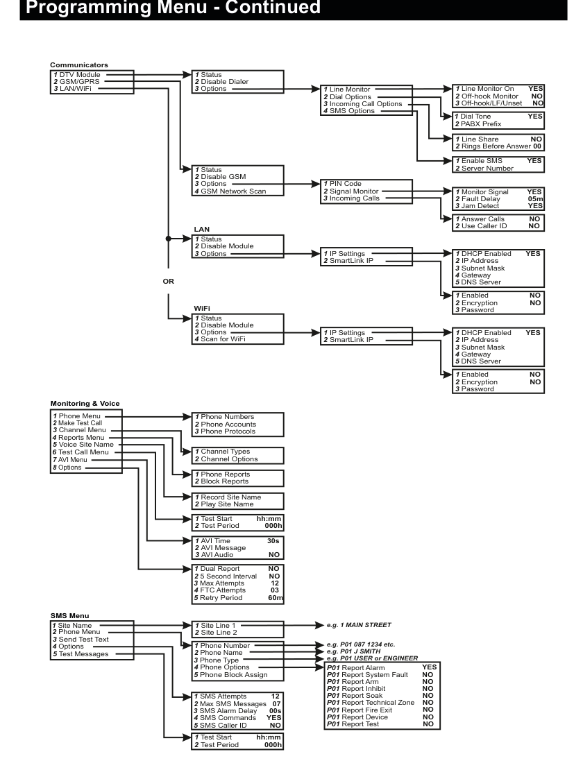
Detailed tree diagram showing the complete 9 Comms Menu structure.
Communicators section (top):
1 DTV Module/2 GSM/GPRS/3 LAN/WiFi- DTV Module expands to:
1 Status,2 Disable Dialer,3 Options→1 Line Monitor(Line Monitor On YES, Off-hook Monitor NO, Off-hook/LF/Unset NO),2 Dial Options(Dial Tone YES, PABX Prefix),3 Incoming Call Options(Line Share NO, Rings Before Answer 00),4 SMS Options(Enable SMS YES, Server Number) - GSM/GPRS expands to:
1 Status,2 Disable GSM,3 Options→1 PIN Code,2 Signal Monitor(Monitor Signal YES, Fault Delay 05m, Jam Detect YES),3 Incoming Calls(Answer Calls NO, Use Caller ID NO),4 GSM Network Scan - LAN and WiFi shown separately with identical sub-structure:
1 Status,2 Disable Module,3 Options→1 IP Settings(DHCP Enabled YES, IP Address, Subnet Mask, Gateway, DNS Server),2 SmartLink IP(Enabled NO, Encryption NO, Password). WiFi also has4 Scan for WiFi.
Monitoring & Voice section (middle):
1 Phone Menu→1 Phone Numbers,2 Phone Accounts,3 Phone Protocols2 Make Test Call3 Channel Menu→1 Channel Types,2 Channel Options4 Reports Menu→1 Phone Reports,2 Block Reports5 Voice Site Name→1 Record Site Name,2 Play Site Name6 Test Call Menu→1 Test Starthh:mm,2 Test Period000h7 AVI Menu→1 AVI Time30s,2 AVI Message,3 AVI AudioNO8 Options→1 Dual ReportNO,2 5 Second IntervalNO,3 Max Attempts12,4 FTC Attempts03,5 Retry Period60m
SMS Menu section (bottom):
1 Site Name→1 Site Line 1,2 Site Line 2(e.g. "1 MAIN STREET")2 Phone Menu→1 Phone Number,2 Phone Name,3 Phone Type,4 Phone Options,5 Phone Block Assign- Phone Options defaults: P01 Report Alarm YES, Report System Fault NO, Report Arm NO, Report Inhibit NO, Report Soak NO, Report Technical Zone NO, Report Fire Exit NO, Report Device NO, Report Test NO
3 Send Test Text4 Options→1 SMS Attempts12,2 Max SMS Messages07,3 SMS Alarm Delay00s,4 SMS CommandsYES,5 SMS Caller IDNO5 Test Messages→1 Test Starthh:mm,2 Test Period000h
9 Comms Menu
The Comms Menu has the following top-level structure:
- 1 Comms Overview
- 2 Communicators (DTV, GSM/GPRS, LAN/WiFi)
- 3 Monitoring & Voice
- 4 SMS Menu
- 5 Remote User Menu
- 6 Panel Print Menu
- 7 Serial Port Equip. Menu
- 8 SecureComm Menu
2 Communicators:
- 1 DTV Module
- 1 Status
- 2 Disable Dialer
- 3 Options
- 1 Line Monitor — 1 Line Monitor On (YES), 2 Off-hook Monitor (NO), 3 Off-hook/LF/Unset (NO)
- 2 Dial Options — 1 Dial Tone (YES), 2 PABX Prefix
- 3 Incoming Call Options — 1 Line Share (NO), 2 Rings Before Answer (00)
- 4 SMS Options — 1 Enable SMS (YES), 2 Server Number
- 2 GSM/GPRS
- 1 Status
- 2 Disable GSM
- 3 Options
- 1 PIN Code
- 2 Signal Monitor — 1 Monitor Signal (YES), 2 Fault Delay (05m), 3 Jam Detect (YES)
- 3 Incoming Calls — 1 Answer Calls (NO), 2 Use Caller ID (NO)
- 4 GSM Network Scan
- 3 LAN/WiFi (LAN or WiFi — same sub-menu structure)
- 1 Status
- 2 Disable Module
- 3 Options
- 1 IP Settings — 1 DHCP Enabled (YES), 2 IP Address, 3 Subnet Mask, 4 Gateway, 5 DNS Server
- 2 SmartLink IP — 1 Enabled (NO), 2 Encryption (NO), 3 Password
- 4 Scan for WiFi (WiFi only)
Services:
- Monitoring & Voice
- 1 Phone Menu — 1 Phone Numbers, 2 Phone Accounts, 3 Phone Protocols
- 2 Make Test Call
- 3 Channel Menu — 1 Channel Types, 2 Channel Options
- 4 Reports Menu — 1 Phone Reports, 2 Block Reports
- 5 Voice Site Name — 1 Record Site Name, 2 Play Site Name
- 6 Test Call Menu — 1 Test Start (hh:mm), 2 Test Period (000h)
- 7 AVI Menu — 1 AVI Time (30s), 2 AVI Message, 3 AVI Audio (NO)
- 8 Options — 1 Dual Report (NO), 2 5 Second Interval (NO), 3 Max Attempts (12), 4 FTC Attempts (03), 5 Retry Period (60m)
- SMS Menu
- 1 Site Name — 1 Site Line 1, 2 Site Line 2 (e.g. "1 MAIN STREET")
- 2 Phone Menu — 1 Phone Number, 2 Phone Name, 3 Phone Type, 4 Phone Options, 5 Phone Block Assign
- 3 Send Test Text
- 4 Options — 1 SMS Attempts (12), 2 Max SMS Messages (07), 3 SMS Alarm Delay (00s), 4 SMS Commands (YES), 5 SMS Caller ID (NO)
- 5 Test Messages — 1 Test Start (hh:mm), 2 Test Period (000h)
- 5 Remote User Menu
- 1 Remote User Codes
- 2 Remote User Names
- 3 Remote User Phones
- 6 Panel Print Menu — Printer Port
- 7 Serial Port Equip. Menu
- 8 SecureComm Menu — 1 Status, 2 Disable, 3 Options, 4 IP Monitoring
Quick Key Shortcuts
| Shortcut | Function | Shortcut | Function |
|---|---|---|---|
| 0#1 | User Log | 0*1 | SMS Engineers |
| 0#3 | Walk Test | 0*2 | SMS Log |
| 0#4 | Full Arm | 0*3 | Call PC |
| 0#5 | Quick Arm | 0*4 | PC Direct |
| 0#6 | Toggle Chime | 0*5 | User Check |
| 0#7 | Part Set A | 0*6 | Temporary User |
| 0#8 | Part Set B | 0*7 | Home Alone |
| 0#9 | Bell Test | 0*8 | Outputs |
Reference: Zone & Point Types
| Type | Available Options |
|---|---|
| Alarm | Inhibit, Access, Excl. from Part Set A, Excl. from Part Set B, Double Knock, Soak, Chime, 24 Hour, Perimeter, Remote Test |
| Entry/Exit | Inhibit, Excl. from Part Set A, Excl. from Part Set B, Soak, Chime, Disable BV, Remote Test |
| Panic | Inhibit, Soak, Silent PA, Remote Test |
| Fire | Inhibit, Soak, Remote Test |
| Tamper | Soak, Key Pulse, Remote Test |
| Gas | Inhibit, Soak, 24 Hour, Fire Exit Delay, Remote Test |
| Key | Remote Test |
| Line Fault | (none) |
| Fail To Communicate | (none) |
| Technical | (none) |
| Fire Exit | Unset, Remote Test |
| Exit Terminator | Inhibit, Soak, 24 Hour, Remote Test |
| Shunt Lock | (none) |
All Zone & Point Types: Alarm, Entry/Exit, Panic, Fire, Tamper, Key, Line Fault, Fail to Connect, Unused, Technical 1–8, Exit Terminator, Gas, Shunt Lock* (*UK only), Fire Exit 1–12, Key Part Set A, Key Part Set B
Zone Hardware Types: 01 Non EOL, 02 Single EOL, 03 Dual EOL 4K7, 0X Dual EOL 2K2, 0X Point ID, 0X RF Device, 0X RFI Device
Reference: User Options
Full Set, Unset, Inhibit, Part Set A, Part Set B, Unused, Open/Closed, Home Alone, Auto-Activate, Auto-Arm Full, User Menu, Manager Menu, Output Only, 24 Hour, Code & Prox, Auto-Arm Part Set A, Auto-Arm Part Set B, Timed Access, User Alert
Event Timer Types: Full Set, Unset, Inhibit, Part Set A, Part Set B
Reference: Output Options
Pre-alarm, Alarm, Light, Partguard, Latch, Fire Reset, Perimeter, Tamper, Buzzer, Trouble, Tech 1–8, Fire Exit 1–12, Block 1–8 Buzzer, Pre-Alarm, Block 1–8 Pre-Alarm, Alarm Abort, Block 1–8 Alarm Abort, Mains Delay, Unexpected Open, Unexpected Close, Auto-activate, User Alert, SmartLight, SmartDoor, Unused, Line Fault, Inhibit, B0–B8 Inhibit, Force GSM, Zone/Point MAP, Pulse Gate, Heat, Gates, Aux, Free to Use, Panic Confirmed* (*UK only), Sensor Reset, Internal Bell, External Bell, Alarm, Arm/Disarm, Fire, Panic Alarm, Strobe, B1–B8 Alarm, B0–B8 Arm/Disarm, B1–B8 Internal Bell, B1–B8 External Bell, B1–B8 Strobe
Mapped Output Options: Unset Disable (Y/N), Latched Output (Y/N), Pulsed Output (Y/N), Output Trip Time (sec)
Reference: Remote User Options
| Option | Default |
|---|---|
| Call Back | NO |
| Remote Set | NO |
| Remote Unset | NO |
Default Codes: Engineer Code: 4567, User Code (Ireland): 1111, User Code (UK): 1234