RF-Echo (Wireless Echo Sounder)
Hardware
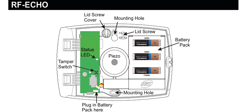
Internal view of the RF-Echo device with lid open. Left side (circuit board): a green PCB with a Tamper Switch at the bottom-left, a Status LED above it, and a connector at the bottom for "Plug in Battery Pack here". Centre: a large circular Piezo sounder element. Right side: a Battery Pack of three Duracell Ultra Lithium CR123A 3V cells (two labelled SIREN, one labelled COMMS). The case has two Mounting Holes (top-right and bottom-centre), a Lid Screw (top-right), and a Lid Cover (top-left). The HKC logo is visible on the case.
| Component | Description |
|---|---|
| Tamper Switch | Detects case opening (bottom-left of PCB) |
| Status LED | Status indicator (on PCB) |
| Piezo | Piezo sounder element (centre of unit) |
| Battery Pack | 3x CR123A 3V Lithium batteries (right side) |
| Mounting Holes | For wall mounting (two locations on case) |
| Lid Screw | Secures lid to case body (top-right) |
| Lid Cover | Screw cover (top-left) |
Key Features
- Recommend that battery is changed every 3 years
- >400m Line-of-sight Radio Range
- Adjustable Volume
- Short-circuit J2 to Test Siren
Add & ID on to the System
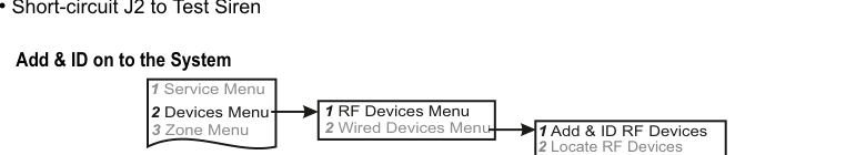
A three-column menu navigation flowchart. First column: 1 Service Menu / 2 Devices Menu / 3 Zone Menu. Arrow leads to second column: 1 RF Devices Menu / 2 Wired Devices Menu. Arrow leads to third column: 1 Add & ID RF Devices / 2 Locate RF Devices / 3 Remove RF Devices.
- To put an RF-Echo on to a SecureWave system go into engineer mode.
- Open the RF-Echo and plug in the battery pack to power it up.
- If you have a second device you can open it too at this stage and plug in its battery pack.
- Don't close their lids just yet.
- Select the Devices Menu, then RF Devs Menu. Next select the Add & Id RF Devs option.
- Next, add and identify the device(s) as RF-Echo.
The sub-menu offers three device types:

A three-column sub-menu flowchart. First column: 1 Add & ID RF Devices / 2 Locate RF Devices / 3 Remove RF Devices. Arrow leads to second column: 1 Add&Id:RF Zones / 2 Add&Id:RF Keyfob / 3 Add&Id:RF Echo (highlighted). Arrow from 3 Add&Id:RF Echo leads to Scanning RF Devs in the third column.
1 Add&Id: RF Zones— add and identify RF zone devices2 Add&Id: RF Keyfob— add and identify RF Keyfobs3 Add&Id: RF Echo— add and identify the RF-Echo
The system displays Devs Found - 000 when it starts scanning and as it finds its first device the display will change to Devs Found - 001. When the system has found all its devices, press PLAY/QUIT.
- Next, close the devices' tamper switches by fitting their lids.
- As you close the devices' tamper switches in sequence, you will hear an audible indication as each device is identified into the system.
The RF-Echo can have a delayed reaction.
RF Device Options (Programmable Settings)
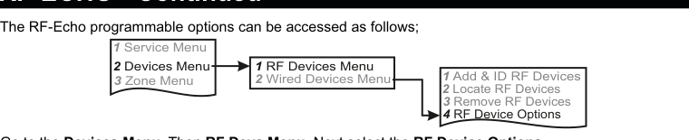
A three-column navigation flowchart. First column: 1 Service Menu / 2 Devices Menu / 3 Zone Menu. Arrow to second column: 1 RF Devices Menu / 2 Wired Devices Menu. Arrow to third column: 1 Add & ID RF Devices / 2 Locate RF Devices / 3 Remove RF Devices / 4 RF Device Options (highlighted).
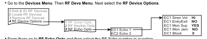
A four-column sub-menu flowchart. First column: 1 Add & ID RF Devices / 2 Locate RF Devices / 3 Remove RF Devices / 4 RF Device Options. Arrow to second column: 1 RF Zone Opts / 2 RF Keyfob Opts / 3 RF Echo Opts (highlighted). Arrow to third column: EC1 Echo 1 / EC2 Echo 2. Arrow to fourth column showing default values: EC1 Siren Vol Hi / EC1 EntryExit NO / EC1 Mon Sup YES / EC1 Mon Jam NO / EC1 Block 0.
The RF-Echo programmable options can be accessed as follows:
Menu navigation: 1 Service Menu → 2 Devices Menu → 1 RF Devices Menu → 4 RF Device Options
Go to the Devices Menu, then RF Devs Menu. Next select the RF Device Options.
From there go to RF Echo Opts and then select the RF-Echo number in question.
Sub-menu path: 4 RF Device Options → 3 RF Echo Opts → Select echo (EC1, EC2, etc.)
Siren Vol (Siren Volume)
You can adjust the device's volume. EC1 Siren Vol can be set to LOW, MED or HI.
| Setting | Description |
|---|---|
| LOW | Low volume |
| MED | Medium volume |
| HI | High volume (default) |
Mon Sup (Monitored Supervisory)
EC1 Mon Sup (Monitored Supervisory signal) is defaulted to YES. When the device is "lost" for a prolonged period of time, a supervisory alarm is flagged by the panel. This can be turned off by selecting NO.
| Setting | Description |
|---|---|
| Mon Sup YES | Supervisory alarm enabled (default) |
| Mon Sup NO | Supervisory alarm disabled |
We recommend that this feature is left as YES.
Mon Jam (Monitor for Jamming)
EC1 Mon Jam (Monitor for Jamming), when set to YES, will trigger the siren for 15 minutes in the RF-Echo if there is a breakdown in the communications link with the panel and a jamming signal detected at 868MHz.
| Setting | Description |
|---|---|
| Mon Jam NO | Jamming detection disabled (default) |
| Mon Jam YES | Siren triggers for 15 min on jamming detection |
EntryExit
EC1 EntryExit can be set to YES. This allows the RF-Echo to behave like the Entry/Exit buzzer. By default it is set to NO in Ireland and YES in the UK.
| Setting | Description |
|---|---|
| EntryExit NO | No Entry/Exit buzzer (default Ireland) |
| EntryExit YES | Acts as Entry/Exit buzzer (default UK) |
Block
EC1 Block is where you can assign the device to a specific block (anywhere between 0 and 8).
| Setting | Description |
|---|---|
| Block 0 | Assigned to block 0 (default) |
| Block 0–8 | Assignable to any block from 0 to 8 |
Testing the RF-Echo
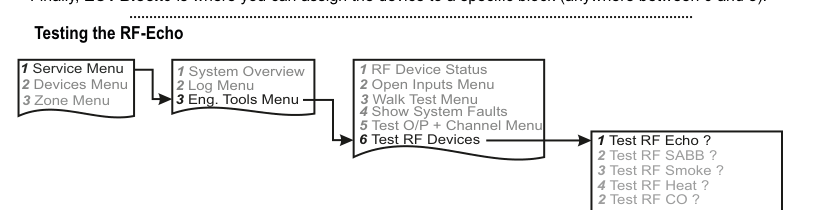
A four-column menu navigation flowchart. First column: 1 Service Menu / 2 Devices Menu / 3 Zone Menu. Arrow to second column: 1 System Overview / 2 Log Menu / 3 Eng. Tools Menu. Arrow to third column: 1 RF Device Status / 2 Open Inputs Menu / 3 Walk Test Menu / 4 Show System Faults / 5 Test O/P + Channel Menu / 6 Test RF Devices (highlighted). Arrow to fourth column: 1 Test RF Echo ? / 2 Test RF SABB ? / 3 Test RF Smoke ? / 4 Test RF Heat ? / 2 Test RF CO ?.
Menu path: 1 Service Menu → 3 Eng. Tools Menu → 6 Test RF Devices → 1 Test RF Echo ?
Go to Test RF Devices and select Test RF Echo ?. Select the RF-Echo you want to test and press REC/YES to activate and deactivate the siren.
Siren Test (at the device)
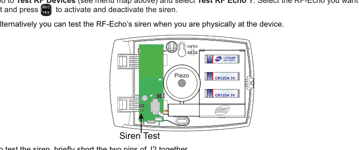
An internal view of the RF-Echo with the lid open, showing the PCB (left), Piezo sounder (centre), and battery pack (right, with CR123A 3V batteries). An arrow points to the J2 test pins on the PCB, labelled "Siren Test". Briefly shorting these two pins together activates the siren.
Alternatively you can test the RF-Echo's siren when you are physically at the device. To test the siren, briefly short the two pins of J2 together.
Be aware that the siren test can be very loud.
Locate RF Devices
Menu path: 2 Devices Menu → 1 RF Devices Menu → 2 Locate RF Devices
Remove RF Devices
Menu path: 2 Devices Menu → 1 RF Devices Menu → 3 Remove RF Devices
Specifications
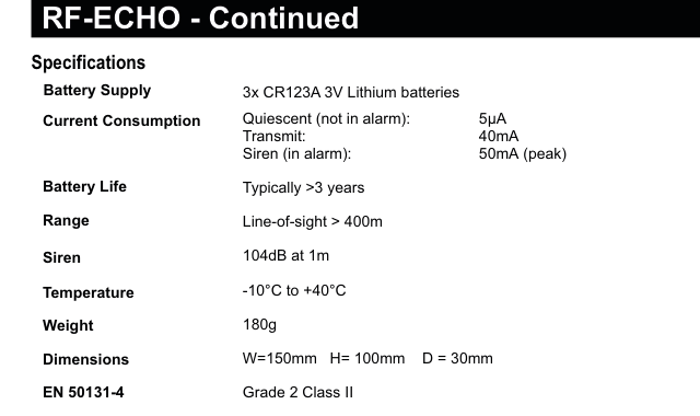
A two-column specifications table with parameter names in bold on the left and values on the right. Lists: Battery Supply — 3x CR123A 3V Lithium batteries; Current Consumption — Quiescent (not in alarm): 5µA, Transmit: 40mA, Siren (in alarm): 50mA (peak); Battery Life — Typically >3 years; Range — Line-of-sight > 400m; Siren — 104dB at 1m; Temperature — -10°C to +40°C; Weight — 180g; Dimensions — W=150mm H=100mm D=30mm; EN 50131-4 — Grade 2 Class II.
| Parameter | Value |
|---|---|
| Battery Supply | 3x CR123A 3V Lithium batteries |
| Current Consumption | Quiescent (not in alarm): 5µA / Transmit: 40mA / Siren (in alarm): 50mA (peak) |
| Battery Life | Typically >3 years |
| Range | Line-of-sight > 400m |
| Siren | 104dB at 1m |
| Temperature | -10°C to +40°C |
| Weight | 180g |
| Dimensions | W=150mm H=100mm D=30mm |
| EN 50131-4 | Grade 2 Class II |