RF-PIRCAM (Wireless PIR Camera)
Hardware
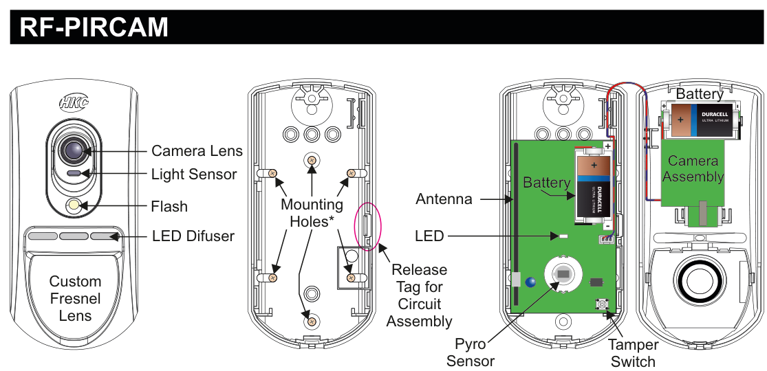
Three views of the RF-PIRCAM device. Front view (left): a rounded rectangular unit with a Camera Lens at the top, a Light Sensor below it, a Flash LED, an LED Diffuser window, and a large Custom Fresnel Lens covering the lower portion. Internal view (centre): the rear of the circuit board showing Mounting Holes (marked with asterisk) at top, a Release Tag for Circuit Assembly, an LED, and an Antenna. Rear case (right): shows two Battery slots (each holding an Energizer Ultra Lithium cell, polarity marked + and −), a Camera Assembly module, a Pyro Sensor, and a Tamper Switch.
| Component | Description |
|---|---|
| Camera Lens | High quality colour camera lens (top of front face) |
| Light Sensor | Ambient light detection sensor for auto flash mode |
| Flash | White LED flash for low-light image capture |
| LED Diffuser | Front window for status LED visibility |
| Custom Fresnel Lens | PIR detection lens (lower front face) |
| Mounting Holes | For wall mounting (rear case, marked with asterisk) |
| Release Tag | Pull tag for circuit board assembly removal |
| LED | Status indicator (on circuit board) |
| Antenna | RF communication antenna (on circuit board) |
| Battery | Two Energizer Ultra Lithium, 3Vdc, 1400mAh (rear case) |
| Camera Assembly | Colour VGA camera module (rear case) |
| Pyro Sensor | Passive infrared detection element (rear case) |
| Tamper Switch | Detects case opening (rear case) |
Key Features
- 15m Pyro Detection
- High Quality Colour Camera with white LED for low light
- Very Low Current Consumption
- Long Battery Life (typically up to 3 years)
- >400m Line-of-sight Radio Range
- Close-in Detection
- Adjustable Sensitivity
- Noise Immunity
- Temperature Compensation
Add & ID on to the System

A three-column menu navigation flowchart. First column: 1 Service Menu / 2 Devices Menu / 3 Zone Menu. Arrow leads to second column: 1 RF Devices Menu / 2 Wired Devices Menu. A warning icon with red text states: "RF-PIRCAM can connect to RF-Expander". Arrow leads to third column: 1 Add & ID RF Devices / 2 Locate RF Devices / 3 Remove RF Devices.
RF-PIRCAM can connect to RF-Expander.
- To put an RF-PIRCAM on to a SecureWave system go into engineer mode. Select the Devices Menu, then RF Devs Menu. Next, select the Add & Id RF Devs option.
- Now you have a choice to add and identify the RF-PIRCAM and map it onto either a zone or point location.
To conserve zones it would be best to add and ID your RF-PIRCAMs onto Points (of which there are 40) first before you assign them to Zones.
The sub-menu offers two device types:

A three-column sub-menu flowchart. First column: 1 Add & ID RF Devices / 2 Locate RF Devices / 3 Remove RF Devices. Arrow leads to second column: 1 Add&Id:RF Zones / 2 Add&Id:RF Points. Each option has an arrow leading to Scanning RF Devs in the third column.
1 Add&Id: RF Zones— add and identify the RF-PIRCAM as a zone device2 Add&Id: RF Points— add and identify the RF-PIRCAM as a point device
The system displays Devs Found - 000 when it starts scanning and as it finds its first device the display will change to Devs Found - 001. When the system has found all its devices you will be prompted to close the devices' tamper switches.
A full scan will take about a minute and may be halted at any time by pressing PLAY/QUIT.
Close the devices' tamper switches in sequence. You will hear an audible indication as each device is identified into the system.
The RF-Echo can have a delayed reaction.
RF Device Options (Programmable Settings)

Flowchart (top-level navigation): Three columns. First column: 1 Service Menu / 2 Devices Menu / 3 Zone Menu. Arrow to second column: 1 RF Devices Menu / 2 Wired Devices Menu. Arrow to third column: 1 Add & ID RF Devices / 2 Locate RF Devices / 3 Remove RF Devices / 4 RF Devs Options (highlighted).

Flowchart (sub-menu): Three columns. First column: 1 Add & ID RF Devices / 2 Locate RF Devices / 3 Remove RF Devices / 4 RF Devs Options. Arrow to second column: 1 RF Zone Opts / 2 RF Point Opts. Arrow to third column showing default values: 1 Settings — MED / 2 Mon Sup — YES / 3 Flash — ON.
The RF-PIRCAM's programmable options can be accessed as follows:
Menu navigation: 1 Service Menu → 2 Devices Menu → 1 RF Devices Menu → 4 RF Devs Options
To get to either the RF-Zones or RF-Points options menu; select the Devices Menu. Then RF Devs Menu. Next select the RF Devs Options.
From there go to either the RF Zone Opts or RF Point Opts menu and then select the RF-PIRCAM number in question.
Sub-menu path: 4 RF Devs Options → 1 RF Zone Opts / 2 RF Point Opts → Settings
Sensitivity (Settings)
You can now select the sensitivity of the RF-PIRCAM. The three levels are LOW, MED and HI.
| Setting | Value |
|---|---|
| LOW | Low sensitivity |
| MED | Medium sensitivity (default) |
| HI | High sensitivity |
Monitored Supervisory (Mon Sup)
Another option is Mon Sup (Monitored Supervisory signal) is defaulted to YES. When the device is "lost" for >120 minutes, a supervisory alarm is flagged by the panel. This can be turned off by selecting NO. However, we recommend that this feature is left as YES.
We recommend that this feature is left as YES.
Flash
The final section is Flash. There are three conditions; ON, OFF and AUTO. The default is ON — this means that the RF-PIRCAM always triggers the flash when it takes an image. With OFF there is no flash (unless you are taking a live snapshot) and with AUTO, the flash is only triggered when the room is dark.
| Setting | Description |
|---|---|
| ON | Flash always triggers when an image is taken (default) |
| OFF | No flash (unless taking a live snapshot) |
| AUTO | Flash only triggers when the room is dark |
RF Camera Options

A two-column menu navigation flowchart. First column lists all RF Devices Menu items: 1 Add & ID RF Devices / 2 Locate RF Devices / 3 Remove RF Devices / 4 RF Devs Options / 5 RF System Options / 6 RF Camera Options (highlighted). Arrow to second column: 1 Image Size / 2 Color / 3 Num Images / 4 Live Images.
Menu path: 2 Devices Menu → 1 RF Devices Menu → 6 RF Camera Options
There are 4 sections to the RF Camera Opts menu:
Image Size
Image Size is defaulted to VGA which is 640x480 pixels. If you press NO you can select QVGA which has a lower resolution of 320x240 pixels but has a quicker transmission time.
Color
Color is defaulted to YES. You can select black and white by pressing NO but unless there are specific site-related reasons for choosing black and white we recommend keeping the colour on.
Num Images (Number of Images)
Num images is shorthand for "Number of images" and is defaulted to 3. When the system is armed and the PIRCAM is triggered, 3 snapshots are taken at 1 second intervals. This number can be changed by pressing YES and then pressing any number between 1 to 5.
Live Images
Live images is defaulted to NO. When YES is selected, you can take a snapshot on your smart phone whenever you want.
To utilise the camera, the system needs to be connected to SecureComm and have the HKC app.
Locate RF Devices

Flowchart: Three columns. First column: 1 RF Devices Menu / 2 Wired Devices Menu. Arrow to second column: 1 Add & ID RF Devices / 2 Locate RF Devices (highlighted) / 3 Remove RF Devices. Arrow to third column: 1 Locate:RF Zones / 2 Locate:RF Points.
To locate an RF-PIRCAM go to the Devices Menu in engineer mode and follow the menu path below.
Menu path: 2 Devices Menu → 1 RF Devices Menu → 2 Locate RF Devices
Then select:
1 Locate: RF Zones→ select zone number2 Locate: RF Points→ select point number
In the Locate: RF Zones or Locate: RF Points you will observe the following:
PIR located — LED turns on/off every second.
- You will automatically be brought to either zone 1 or the first point (P50).
- When you want to move on to the next zone or point then press # (next).
Remove RF Devices

A three-column menu navigation flowchart. First column: 1 RF Devices Menu / 2 Wired Devices Menu. Arrow to second column: 1 Add & ID RF Devices / 2 Locate RF Devices / 3 Remove RF Devices (highlighted). Arrow to third column: 1 Remove:RF Zones / 2 Remove:RF Points.
Menu path: 2 Devices Menu → 1 RF Devices Menu → 3 Remove RF Devices
Then select:
-
1 Remove: RF Zones→ select zone number -
2 Remove: RF Points→ select point number -
To remove an RF-PIRCAM go to the Devices Menu in engineer mode and follow the menu path above.
-
You will automatically be brought to either zone 1 or the first point (P50).
-
Go to the zone or point you want to remove and press REC/YES.
Range of Detection
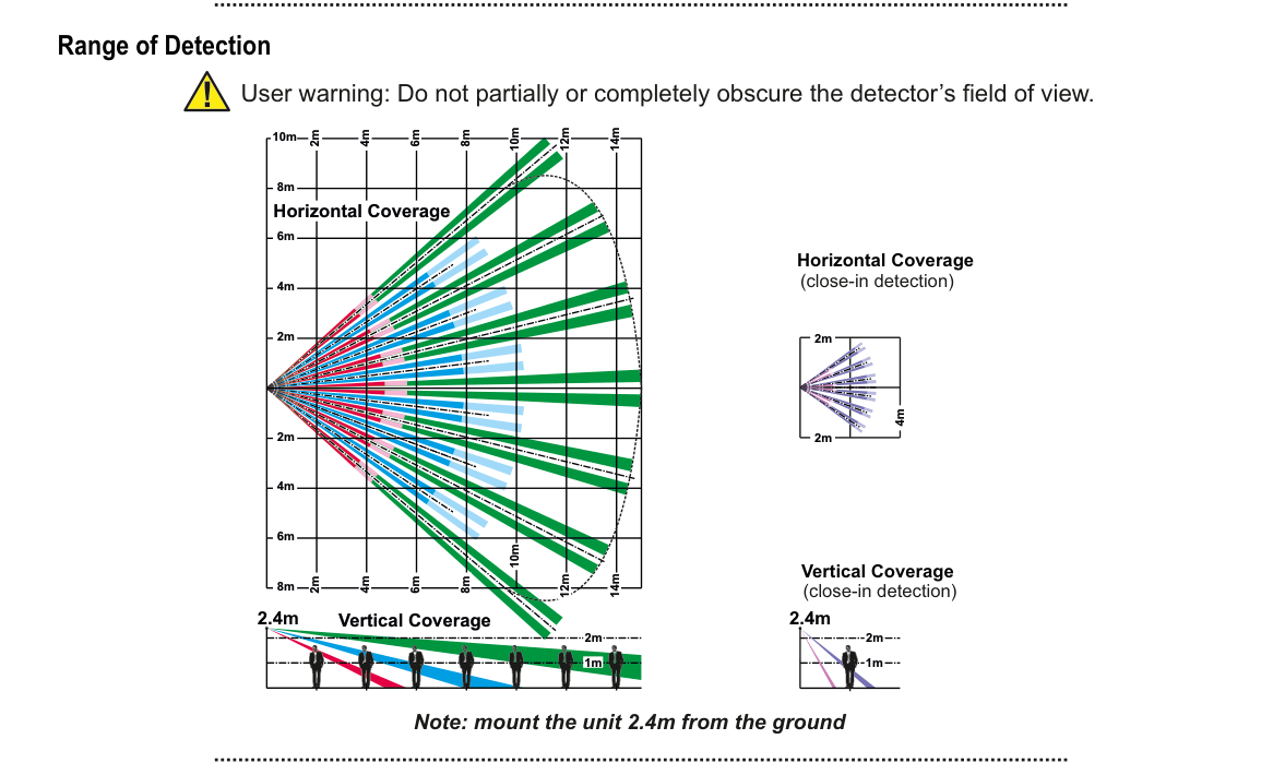
"Range of Detection" heading with a warning icon: "User warning: Do not partially or completely obscure the detector's field of view."
Four coverage diagrams are shown:
-
Horizontal Coverage (top-down view, left): A large fan-shaped detection pattern with multiple coloured beams (blue, red, green, magenta) radiating outward. Distance markers at 2m, 4m, 6m, 8m, 10m, 12m, and 14m intervals along the centre axis. The fan spans several metres wide at maximum range.
-
Horizontal Coverage (close-in detection) (top-down view, right): A smaller concentrated detection pattern extending approximately 2m in front of the sensor with a width of approximately 4m.
-
Vertical Coverage (side view, bottom-left): Mounted at 2.4m height, beams angle downward from the sensor to the floor. Distance markers along the floor at 2m intervals. A green ground-level line shows detection reaching 14m outward.
-
Vertical Coverage (close-in detection) (side view, bottom-right): Mounted at 2.4m height, short-range beams covering approximately 1m–2m directly below the sensor.
"Note: mount the unit 2.4m from the ground" appears at bottom centre.
User warning: Do not partially or completely obscure the detector's field of view.
Horizontal Coverage (top-down view):
- Main detection: fan-shaped pattern with multiple coloured beams extending to 14m, with coverage zones at 2m, 4m, 6m, 8m, 10m, 12m, and 14m
- Close-in detection: concentrated coverage within approximately 2m × 4m directly in front of the sensor
Vertical Coverage (side view, mounted at 2.4m):
- Main detection: beams angle downward from 2.4m mounting height to floor level, reaching out to 14m horizontally with markers at 2m intervals
- Close-in detection: short-range beams covering 1m–2m below the sensor
Mount the unit 2.4m from the ground.
Specifications
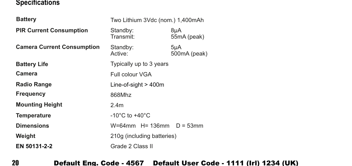
A two-column specifications table with parameter names in bold on the left and values on the right. Lists: Battery — Two Lithium 3Vdc (nom.) 1,400mAh; PIR Current Consumption — Standby: 8µA, Transmit: 55mA (peak); Camera Current Consumption — Standby: 5µA, Active: 500mA (peak); Battery Life — Typically up to 3 years; Camera — Full colour VGA; Radio Range — Line-of-sight > 400m; Frequency — 868Mhz; Mounting Height — 2.4m; Temperature — -10°C to +40°C; Dimensions — W=64mm H=136mm D=53mm; Weight — 210g (including batteries); EN 50131-2-2 — Grade 2 Class II.
| Parameter | Value |
|---|---|
| Battery | Two Lithium 3Vdc (nom.) 1,400mAh |
| PIR Current Consumption | Standby: 8µA / Transmit: 55mA (peak) |
| Camera Current Consumption | Standby: 5µA / Active: 500mA (peak) |
| Battery Life | Typically up to 3 years |
| Camera | Full colour VGA |
| Radio Range | Line-of-sight > 400m |
| Frequency | 868MHz |
| Mounting Height | 2.4m |
| Temperature | -10°C to +40°C |
| Dimensions | W=64mm H=136mm D=53mm |
| Weight | 210g (including batteries) |
| EN 50131-2-2 | Grade 2 Class II |