RF-Contact/Sensor (Wireless Contact Sensor)
Hardware
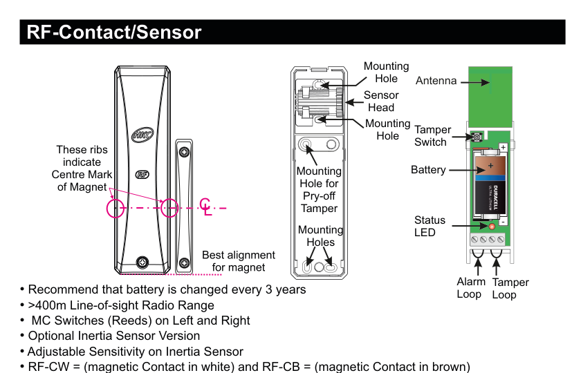
Front view (left): slim door/window contact sensor with HKC logo; ribs on the magnet indicate the centre mark for alignment. Rear case (centre): shows Mounting Hole (top), Sensor Head, Mounting Hole, Mounting Hole for Pry-off Tamper, and Mounting Holes (bottom), with "Best alignment for magnet" indicator. Internal view (right): shows Antenna (green PCB, top), Tamper Switch, Battery (Ultra Lithium 2/3A, 3V), Status LED, and terminal connections for Alarm Loop and Tamper Loop at the bottom.
| Component | Description |
|---|---|
| Mounting Holes | For wall/frame mounting (rear case, multiple positions) |
| Sensor Head | Optional inertia sensor attachment point (rear case) |
| Mounting Hole for Pry-off Tamper | Detects device removal from surface |
| Magnet Centre Mark | Ribs on front case indicate alignment point for magnet |
| Antenna | RF communication antenna (green PCB, internal top) |
| Tamper Switch | Detects case opening (internal) |
| Battery | Ultra Lithium, 3Vdc, 2/3A size, 1400mAh |
| Status LED | Status indicator (internal, bottom) |
| Alarm Loop | Terminal for wired alarm loop connection |
| Tamper Loop | Terminal for wired tamper loop connection |
Key Features
- Recommend that battery is changed every 3 years
- >400m Line-of-sight Radio Range
- MC Switches (Reeds) on Left and Right
- Optional Inertia Sensor Version
- Adjustable Sensitivity on Inertia Sensor
- RF-CW = (magnetic Contact in white) and RF-CB = (magnetic Contact in brown)
- RF-CSW = (MC & inertia Sensor in white) and RF-CSB = (MC & inertia Sensor in brown)
Add & ID on to the System
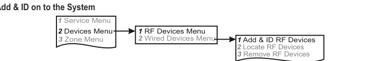
A three-column menu navigation flowchart. First column: 1 Service Menu / 2 Devices Menu (highlighted) / 3 Zone Menu. Arrow leads to second column: 1 RF Devices Menu (highlighted) / 2 Wired Devices Menu. Arrow leads to third column: 1 Add & ID RF Devices (highlighted) / 2 Locate RF Devices / 3 Remove RF Devices.
Procedure:
- Enter engineer mode on the SecureWave system.
- Open the RF-Cx or RF-CSx and pull the isolator away from the battery — this powers it up.
- If you have multiple devices, open them all at this stage and remove their isolators. Don't close their lids yet.
- Navigate to: Devices Menu → RF Devs Menu → Add & Id RF Devs.
- Add and identify the RF-Cx or RF-CSx as a zone. The sub-menu offers three device types:

A three-column sub-menu flowchart. First column: 1 Add & ID RF Devices (highlighted) / 2 Locate RF Devices / 3 Remove RF Devices. Arrow leads to second column: 1 Add&Id:RF Zones (highlighted) / 2 Add&Id:RF Keyfob / 3 Add&Id:RF Echo. Arrow from 1 Add&Id:RF Zones leads to Scanning RF Devs in the third column.
1 Add&Id: RF Zones— add zone devices (contact sensor, PIR, etc.)2 Add&Id: RF Keyfob— add keyfob devices3 Add&Id: RF Echo— add echo (repeater) devices
- The system displays
Devs Found - 000when scanning starts. As it finds devices, the count increments (e.g.Devs Found - 001). - When all devices are found, press PLAY/QUIT.
- Select the zone number to be added and identified.
- Close the devices' tamper switches by fitting their lids.
- As you close each tamper switch in sequence, you will hear an audible indication as each device is identified into the system.
The RF-Echo can have a delayed reaction.
RF Device Options (Programmable Settings)
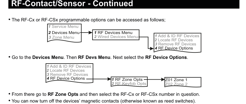
Two menu flowcharts: (1) Main navigation: Service Menu → Devices Menu → RF Devices Menu → RF Device Options (option 4). (2) Sub-menu: RF Device Options → RF Zone Opts (option 1) / RF Keyfob Opts (option 2) → Zone selection (e.g. Z01 Zone 1, Z02 Zone 2). Below the diagrams: instructions for accessing device options, controlling reed switches, and monitored supervisory settings.
Menu path: 1 Service Menu → 2 Devices Menu → 1 RF Devices Menu → 4 RF Device Options
Then select:
1 RF Zone Opts→ select zone number (e.g.Z01 Zone 1)2 RF Keyfob Opts→ select keyfob number (e.g.Z02 Zone 2)
Reed Switches (Magnetic Contacts)
You can turn off the devices' magnetic contacts (otherwise known as reed switches). Selecting Reeds ON NO turns them off.
Monitored Supervisory (Mon Sup)
The Mon Sup (Monitored Supervisory) signal is defaulted to YES. When the device is "lost" for a prolonged period of time, a supervisory alarm is flagged by the panel. This can be turned off by selecting NO.
We recommend that this feature is left as YES.
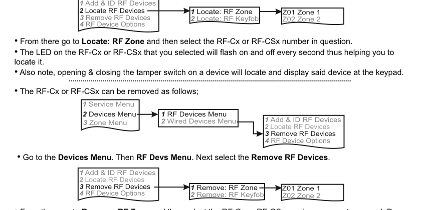
Locate RF Devices
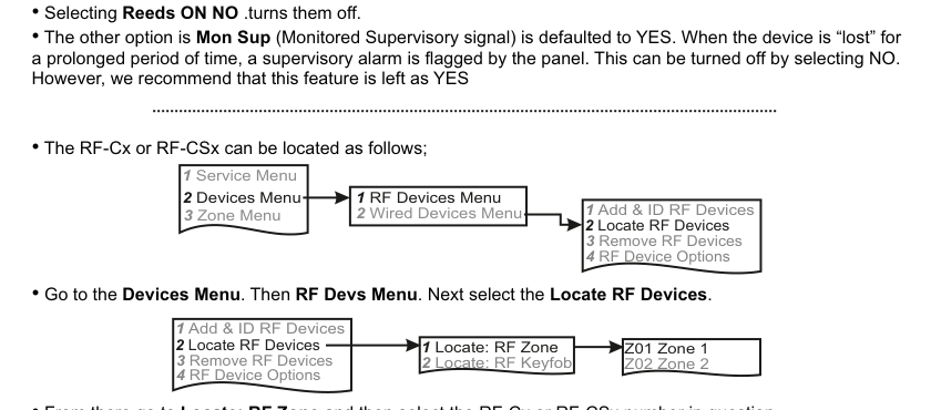
Two menu flowcharts: (1) Main navigation: Service Menu → Devices Menu → RF Devices Menu → Locate RF Devices (option 2). (2) Sub-menu: Locate RF Devices → Locate: RF Zone (option 1) / Locate: RF Keyfob (option 2) → Zone selection (e.g. Z01 Zone 1, Z02 Zone 2). Below the diagrams: instructions for locating devices.
Menu path: 1 Service Menu → 2 Devices Menu → 1 RF Devices Menu → 2 Locate RF Devices
Then select:
1 Locate: RF Zone→ select zone number2 Locate: RF Keyfob→ select keyfob number
The LED on the selected RF-Cx or RF-CSx will flash on and off every second, helping you to locate it.
Opening and closing the tamper switch on a device will also locate and display that device at the keypad.
Remove RF Devices
Two menu flowcharts: (1) Main navigation: Service Menu → Devices Menu → RF Devices Menu → Remove RF Devices (option 3). (2) Sub-menu: Remove RF Devices → Remove: RF Zone (option 1) / Remove: RF Keyfob (option 2) → Zone selection (e.g. Z01 Zone 1, Z02 Zone 2). Below the diagrams: instructions for removing devices.
Menu path: 1 Service Menu → 2 Devices Menu → 1 RF Devices Menu → 3 Remove RF Devices
Then select:
1 Remove: RF Zone→ select zone number2 Remove: RF Keyfob→ select keyfob number
Press YES to select the device for removal, then press YES again to confirm removal.
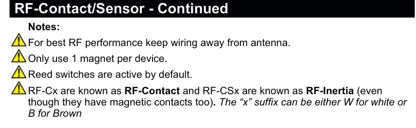
Important Notes
Warning notes page showing four bullet points with warning icons: (1) For best RF performance keep wiring away from antenna. (2) Only use 1 magnet per device. (3) Reed switches are active by default. (4) RF-Cx are known as RF-Contact and RF-CSx are known as RF-Inertia (even though they have magnetic contacts too). The "x" suffix can be either W for white or B for brown.
- For best RF performance keep wiring away from antenna.
- Only use 1 magnet per device.
- Reed switches are active by default.
- RF-Cx are known as RF-Contact and RF-CSx are known as RF-Inertia (even though they have magnetic contacts too). The "x" suffix can be either W for white or B for brown.
Inertia Sensor Mounting
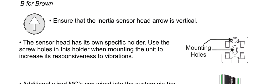
Shows the inertia sensor arrow orientation icon (arrow pointing up inside a circle), the sensor head holder with mounting holes, and instructions for proper mounting.
- Ensure that the inertia sensor head arrow is vertical.
- The sensor head has its own specific holder. Use the screw holes in this holder when mounting the unit to increase its responsiveness to vibrations.
Wired Magnetic Contact (Additional)
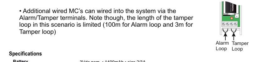
Internal view of the RF-Contact/Sensor PCB showing the battery, Alarm Loop terminal, and Tamper Loop terminal at the bottom. Additional wired magnetic contacts can be connected via these terminals.
Additional wired MC's can be wired into the system via the Alarm/Tamper terminals. Note though, the length of the tamper loop in this scenario is limited (100m for Alarm loop and 3m for Tamper loop).
Specifications
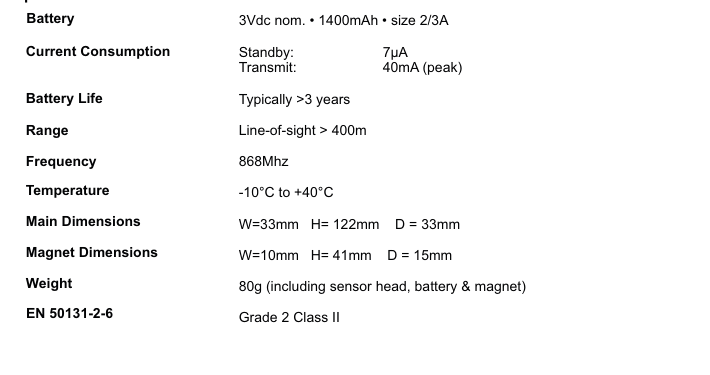
A two-column specifications table with parameter names on the left and values on the right. Lists: Battery — 3Vdc nom. · 1400mAh · size 2/3A; Current Consumption — Standby: 7µA, Transmit: 40mA (peak); Battery Life — Typically >3 years; Range — Line-of-sight > 400m; Frequency — 868MHz; Temperature — -10°C to +40°C; Main Dimensions — W=33mm H=122mm D=33mm; Magnet Dimensions — W=10mm H=41mm D=15mm; Weight — 80g (including sensor head, battery & magnet); EN 50131-2-6 — Grade 2 Class II.
| Parameter | Value |
|---|---|
| Battery | 3Vdc nom. · 1400mAh · size 2/3A |
| Current Consumption | Standby: 7µA / Transmit: 40mA (peak) |
| Battery Life | Typically >3 years |
| Range | Line-of-sight > 400m |
| Frequency | 868MHz |
| Temperature | -10°C to +40°C |
| Main Dimensions | W=33mm H=122mm D=33mm |
| Magnet Dimensions | W=10mm H=41mm D=15mm |
| Weight | 80g (including sensor head, battery & magnet) |
| EN 50131-2-6 | Grade 2 Class II |