Communications Overview
91 Comms Overview
Press YES to see how the Digi Dialler, GSM Module, LAN Module, Monitoring Station details, SMS etc. are configured.
There are 3 sections to Communicators; the DTV Module, the GSM/GPRS Module and LAN/WiFi Module. Before going into each one in detail please see how they are physically connected to the system below (the LAN Module may also be known as the Ethernet Adapter is on the next page along with the WiFi Card).
92 Communicators
Remove the mains and battery supply before fitting the DTV, GSM-Q or GSM-WiFi. Once the hardware is physically fitted and powered-up and you enter the relevant programming menu you will be prompted to activate the device in question.
When both land-line dialler and plug-on GSM unit are operational, Monitoring Station and Voice calls are normally routed on the land-line and SMS functions are normally handled by the GSM unit. If one system fails, the other system will take over its functions. However, the land-line dialler cannot handle in-coming SMS commands or send text messages abroad.
There is no Remote User Code by default. Therefore, if you want remote access to your system, then you need to program one into the panel. Go to Rem. User Code, this is to be found in Remote User Menu, a sub-menu of the Comms Menu. See page 101.
DTV & GSM Connection Diagram
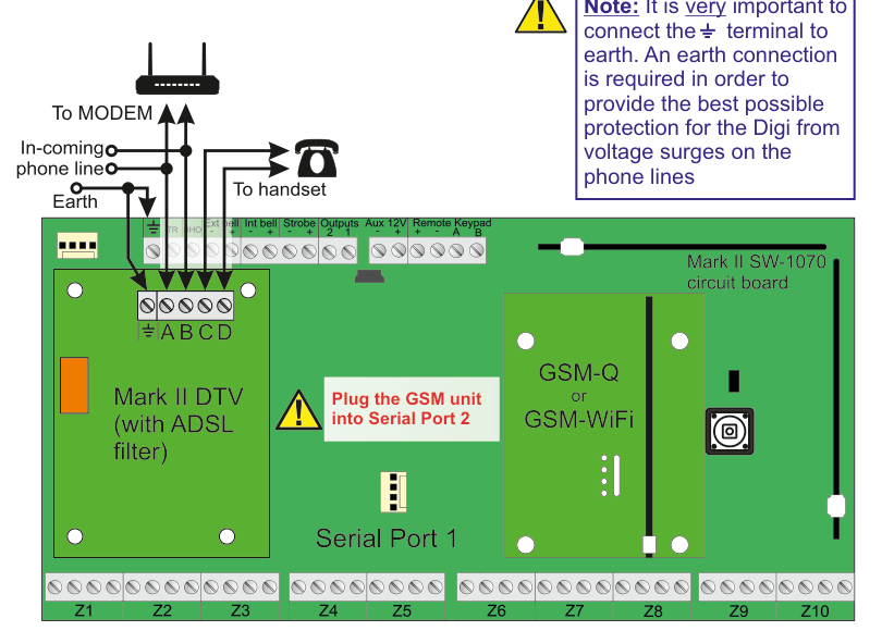
Hardware connection diagram showing the Mark II SW-1070 circuit board with DTV and GSM modules:
- Top left: A router/modem connected via cable. Lines show "To MODEM" and "In-coming phone line" connections, with a branch "To handset" going to a telephone icon. An "Earth" connection is also shown.
- Left side of board: The Mark II DTV (with ADSL filter) module is installed, with terminals labeled
⏚ A B C D(earth, and data terminals A through D). - Centre of board: A yellow warning triangle with text: "Plug the GSM unit into Serial Port 2". Serial Port 1 is labeled below.
- Right side of board: The GSM-Q or GSM-WiFi module plugs into the board area near Serial Port 2.
- Top of board: Terminal strip showing
Ext bell,Int bell,Strobe,Outputs 2 1,Aux 12V,Remote Keypad A B. - Bottom of board: Zone terminals
Z1throughZ10. - Yellow note box (top right): "It is very important to connect the ⏚ terminal to earth. An earth connection is required in order to provide the best possible protection for the Digi from voltage surges on the phone lines."
It is very important to connect the ⏚ terminal to earth. An earth connection is required in order to provide the best possible protection for the Digi from voltage surges on the phone lines.
LAN Module (Ethernet) Installation
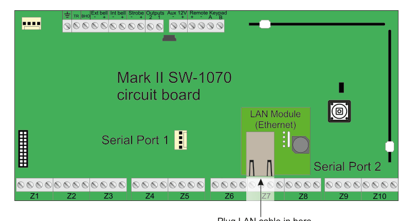
Hardware diagram showing the Mark II SW-1070 circuit board with the LAN Module (Ethernet) installed:
- The LAN Module (Ethernet) card is plugged into the board in the area between Serial Port 1 and Serial Port 2 (right-centre area).
- Serial Port 1 is labeled on the left-centre of the board.
- Serial Port 2 is labeled on the lower-right of the board.
- An arrow at the bottom points to the LAN port with the label "Plug LAN cable in here".
- The board shows terminal strips along the top (
Ext bell,Int bell,Strobe,Outputs 2 1,Aux 12V,Remote Keypad A B) and zone terminalsZ1throughZ10along the bottom.
Remove the mains and battery supply before fitting the LAN-Card. Once the hardware is physically fitted and powered-up and you enter the relevant programming menu you will be prompted to activate the device in question.
WiFi Module Installation
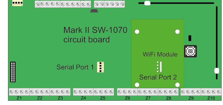
Hardware diagram showing the Mark II SW-1070 circuit board with the WiFi Module installed:
- The WiFi Module card is plugged into the board in the same area as the LAN Module (right-centre), labeled "WiFi Module".
- Serial Port 1 is labeled on the left-centre of the board.
- Serial Port 2 is labeled on the lower-right of the board.
- The board shows the same terminal strips along the top and zone terminals
Z1throughZ10along the bottom.
Remove the mains and battery supply before fitting the WiFi-Card. Once the hardware is physically fitted and powered-up and you enter the relevant programming menu you will be prompted to activate the device in question.
You cannot have the LAN and WiFi cards plugged-in together. You must pick one type of card.