RF-HD (Wireless Heat Detector)
A Heat Alarm is an early warning device. Used correctly it can give you and your family valuable extra time to escape in the event of a fire occurring. If the alarm sounds, immediately evacuate the premises before beginning any investigation and/or calling the Fire Brigade.
- Fix the mounting plate in the centre of the ceiling. If possible, keep at least 0.3m from light fittings & walls.
Hardware
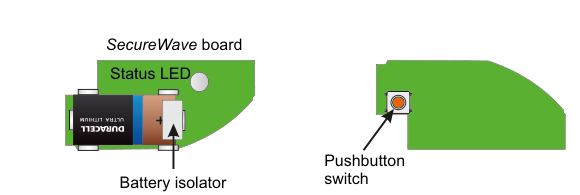
Two views of the RF-Heat Detector components. Left side: the SecureWave board — a green oblong PCB module containing a Duracell Ultra Lithium battery (CR123A-type). A Status LED label points to a small LED on the top of the board. A Battery isolator label points to a tab at the bottom of the board. Right side: the Detector Head — a green dome-shaped unit with a Pushbutton switch (shown as a circular orange/red button) on its face.
| Component | Description |
|---|---|
| SecureWave board | Green PCB module with battery (left side), plugs into detector |
| Status LED | Status indicator on the SecureWave board |
| Battery isolator | Pull-tab to power up the SecureWave board; remove to activate |
| Pushbutton switch | Button on the detector head used for identification |
Key Features
- Recommend that SecureWave battery is changed every 3 years
- Note: Detector Head has own sealed-in battery good for the life of the product i.e. 10 years
- >200m Line-of-sight Radio Range
- Detector Head has own Siren
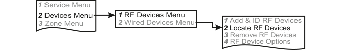
Add & ID on to the System
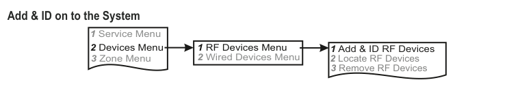
A three-column menu navigation flowchart titled "Add & ID on to the System". First column: 1 Service Menu / 2 Devices Menu (bold) / 3 Zone Menu. Arrow leads to second column: 1 RF Devices Menu (bold) / 2 Wired Devices Menu. Arrow leads to third column: 1 Add & ID RF Devices (bold) / 2 Locate RF Devices / 3 Remove RF Devices.
- To put an RF-Heat on to a SecureWave system go into engineer mode.
- Plug out the SecureWave board to access the battery isolator; remove the isolator. The SecureWave board is now powered-up. Plug it back into the main body of the detector.
- If you have a number of RF-Heats you can open them too at this stage and remove their isolators.
- Select the Devices Menu. Then RF Devs Menu. Next select the Add & Id RF Devs option.
- Next, add and identify the RF-Heat as a zone.
The sub-menu offers three device types:
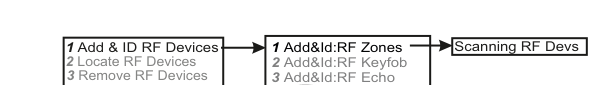
A three-column sub-menu flowchart. First column: 1 Add & ID RF Devices / 2 Locate RF Devices / 3 Remove RF Devices. Arrow leads to second column: 1 Add&Id:RF Zones (bold) / 2 Add&Id:RF Keyfob / 3 Add&Id:RF Echo. Arrow from 1 Add&Id:RF Zones leads to Scanning RF Devs in the third column.
1 Add&Id: RF Zones-- add and identify RF zone devices (select this for RF-Heat)2 Add&Id: RF Keyfob-- add and identify RF Keyfobs3 Add&Id: RF Echo-- add and identify the RF-Echo
The system displays Devs Found - 000 when it starts scanning and as it finds its first device the display will change to Devs Found - 001. When the system has found all its devices, press PLAY/QUIT.
- Select the zone number to be added & ID'ed.
- Next, press the push-button switch for about a second.
- As you press the devices' switches in sequence, you will hear an audible indication as each device is identified into the system.
The RF-Echo can have a delayed reaction.
Please refer to the RF-Heat Installation Manual for further safety advice.
RF Device Options (Programmable Settings)
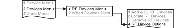
A three-column navigation flowchart. First column: 1 Service Menu / 2 Devices Menu (bold) / 3 Zone Menu. Arrow to second column: 1 RF Devices Menu (bold) / 2 Wired Devices Menu. Arrow to third column: 1 Add & ID RF Devices / 2 Locate RF Devices / 3 Remove RF Devices / 4 RF Device Options (bold/highlighted).
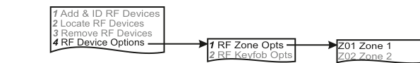
A three-column sub-menu flowchart. First column: 1 Add & ID RF Devices / 2 Locate RF Devices / 3 Remove RF Devices / 4 RF Device Options (bold). Arrow to second column: 1 RF Zone Opts / 2 RF Keyfob Opts. Arrow to third column: Z01 Zone 1 / Z02 Zone 2.
The RF-Heat's one and only programmable option can be accessed as follows:
Menu navigation: 1 Service Menu → 2 Devices Menu → 1 RF Devices Menu → 4 RF Device Options
Go to the Devices Menu. Then RF Devs Menu. Next select the RF Device Options.
From there go to RF Zone Opts and then select the RF-Heat number in question.
Sub-menu path: 4 RF Device Options → 1 RF Zone Opts → Select zone (Z01, Z02, etc.)
Mon Sup (Monitored Supervisory)
The only option is Mon Sup (Monitored Supervisory signal) which is defaulted to YES. When the device is "lost" for a prolonged period of time, a supervisory alarm is flagged by the panel. This can be turned off by selecting NO.
| Setting | Description |
|---|---|
| Mon Sup YES | Supervisory alarm enabled (default) |
| Mon Sup NO | Supervisory alarm disabled |
We recommend that this feature is left as YES.
Locate RF Devices
A three-column navigation flowchart. First column: 1 Service Menu / 2 Devices Menu (bold) / 3 Zone Menu. Arrow to second column: 1 RF Devices Menu (bold) / 2 Wired Devices Menu. Arrow to third column: 1 Add & ID RF Devices / 2 Locate RF Devices (bold/highlighted) / 3 Remove RF Devices / 4 RF Device Options.
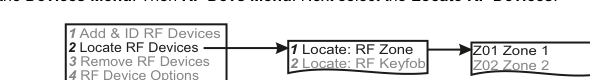
A three-column sub-menu flowchart. First column: 1 Add & ID RF Devices / 2 Locate RF Devices (bold) / 3 Remove RF Devices / 4 RF Device Options. Arrow to second column: 1 Locate: RF Zone / 2 Locate: RF Keyfob. Arrow to third column: Z01 Zone 1 / Z02 Zone 2.
The RF-Heat can be located as follows:
Menu navigation: 1 Service Menu → 2 Devices Menu → 1 RF Devices Menu → 2 Locate RF Devices
Go to the Devices Menu. Then RF Devs Menu. Next select the Locate RF Devices.
From there go to Locate: RF Zone and then select the RF-Heat number in question.
- The LED on the RF-Heat that you selected will flash on and off every second thus helping you to locate it.
- Also note, pressing the switch on a device will locate and display said device at the keypad.
Remove RF Devices
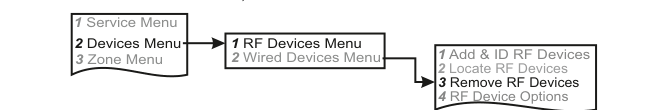
A three-column navigation flowchart. First column: 1 Service Menu / 2 Devices Menu (bold) / 3 Zone Menu. Arrow to second column: 1 RF Devices Menu (bold) / 2 Wired Devices Menu. Arrow to third column: 1 Add & ID RF Devices / 2 Locate RF Devices / 3 Remove RF Devices (bold/highlighted) / 4 RF Device Options.
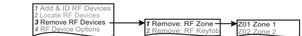
A three-column sub-menu flowchart. First column: 1 Add & ID RF Devices / 2 Locate RF Devices / 3 Remove RF Devices (bold) / 4 RF Device Options. Arrow to second column: 1 Remove: RF Zone / 2 Remove: RF Keyfob. Arrow to third column: Z01 Zone 1 / Z02 Zone 2.
The RF-Heat can be removed as follows:
Menu navigation: 1 Service Menu → 2 Devices Menu → 1 RF Devices Menu → 3 Remove RF Devices
Go to the Devices Menu. Then RF Devs Menu. Next select the Remove RF Devices.
From there go to Remove: RF Zone and then select the RF-Heat number you want removed. Press YES to select this device for removal and press YES again to confirm removal.