Service Menu
11 System Overview
Gives a quick overview of how the system has been configured i.e. what devices are identified, zone information, what fault buzzers are enabled, a summary of the RF network, what blocks are enabled etc.
12 Log Menu

Sub-menu listing for 12 LOG MENU showing two items: 121 View Log and 122 Clear Log.
| Sub-Menu | Description |
|---|---|
| 121 View Log | View the engineer log |
| 122 Clear Log | Clear the engineer log |
Used to view the engineer log and/or clear the engineer log. The log cannot be cleared when the panel is configured to work to the EN 50131 standard. See page 111 for a list of abbreviations.
While viewing the engineer log the 7 and 9 keys can be used to view the previous or next alarm event in the log. This allows you to quickly skip past Unset and Arming events.
13 Engineer Tools Menu
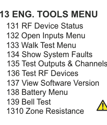
Sub-menu listing for 13 ENG. TOOLS MENU showing ten items: 131 RF Device Status, 132 Open Inputs Menu, 133 Walk Test Menu, 134 Show System Faults, 135 Test Outputs & Channels, 136 Test RF Devices, 137 View Software Version, 138 Battery Menu, 139 Bell Test, and 1310 Zone Resistance.
| Sub-Menu | Description |
|---|---|
| 131 RF Device Status | View wireless device status |
| 132 Open Inputs Menu | View open zones, points or tampers |
| 133 Walk Test Menu | Test detection devices |
| 134 Show System Faults | Overview of fault conditions |
| 135 Test Outputs & Channels | Test system outputs |
| 136 Test RF Devices | Activate sounders in RF devices |
| 137 View Software Version | Check software revisions |
| 138 Battery Menu | Battery current and load test |
| 139 Bell Test | Test buzzer, internal and external sirens |
| 1310 Zone Resistance | Interrogate zone loop resistance |
Engineer Tools Menu has 10 sections and is used to carry out basic system checks.
RF Device Status (131)
RF Device Status informs the installer about whether various wireless devices are ID'ed, online, the condition of their signal strengths etc.
Open Inputs Menu (132)
Open Inputs Menu is used to view open zones, points or tampers.
A Tamper on the hardwired zone configured as Dual EOL will be shown in the Show Open Tampers menu.
Walk Test Menu (133)
Walk Test Menu allows the engineer to test the actual detection devices. The internal sounder & buzzer sounds for 1/2 sec. in the event of an inertia pulse and for 2 sec. for a gross alarm, zone open or tamper alarm. This feature also applies to Point ID sensors too.
Show System Faults (134)
Show System Faults is a quick way for the installer to get an overview of various fault conditions (like open tampers, power outages etc.) that could affect the system's performance.
Test Outputs & Channels (135)
Test Op+Chn Menu (Test Outputs & Channels) has 3 sub-menus:
Test Outputs, as its name suggests, allows you to trigger the various outputs in the system. It has 4 sub-sections; Panel Outputs, Expander Outputs, PSU Outputs (power supplies) and OPC Outputs (output cards). Select the output you are interested in and toggle it ON/OFF by continually pressing YES.
The other 2 Test Op+Chn Menu sub-menus are Test Digi Chns and Test Extend Rpts...
Test Digi Chns (Test Digi Channels) triggers FastFormat channels on the DTV dialler. So, for instance, if you select Panic CLOSE, and then press YES; it changes to Panic OPEN. Assuming you have programmed-in your monitoring station telephone and account numbers, you have now sent a PANIC report to your monitoring station.
This works for any device configured for FastFormat including the 4/8 Channel Dialler, RAR adapter and GSM-Q.
Test Extend Rpts (Test Extended Reports) triggers Contact ID, SIA & Extended SIA reports on the on-board dialler. When you select this you will have a choice of either Test Zone Report or Test Point Report. Go to the section of choice and select the Zone or Point ID number of choice. Then press YES. Assuming you have programmed in the correct protocol and your monitoring station telephone and account numbers, you have now sent a report to your monitoring station as if that particular Zone or Point ID were triggered.
Channels will be returned to their original state on exit from the Test Channel Menu.
Test RF Devices (136)
Test RF Devices allows you to activate the sounders in your RF-SABB, RF-Echo, RF-Smoke, RF-Heat & RF-Carbon Monoxide devices.
View Software Version (137)
View S/W Version (View Software Version) is a feature to check the software revisions in use on various devices connected to the system.
The software versions on remote devices can only be read once they have been identified (ID'ed).
Battery Menu (138)
The Battery Menu has 2 sections.
The first, Batt Current is used to monitor how much current is either going into or coming from the battery. A positive current means the battery is charging while a negative current means it is discharging.
The second, Battery Load Test is used to determine the total system current. During the test the charge/discharge currents will be on the display. Also during the test the system is powered by the battery (and not the mains power supply). This feature lets you know if you are too close to the limits of the mains power supply. The engineer will be prompted to press YES to source all the system current from the battery and NO to go back to the mains power supply.
Bell Test (139)
By selecting Bell Test the panel will activate the buzzer, internal siren(s) and external siren(s) in sequence.
You will be prompted on the display to go outside to hear the external siren(s).
Zone Resistance (1310)
When you select Zone Resistance you can interrogate, by default, each Alarm and Entry/Exit zone to determine its loop resistance - should be used with the Remote Maintenance feature in SmartLink700 to track any trends that would suggest corrosion build-up etc.
You will need V2.1+ software in your 10-Zone expanders to see their loop resistances.
14 Engineer Arm/Disarm

Sub-menu listing for 14 ENG. ARM/DISARM showing five items: 141 Unset ?, 142 Full Set ?, 143 Quick Arm ?, 144 Part Set A ?, and 145 Part Set B ?.
| Sub-Menu | Description |
|---|---|
| 141 Unset ? | Unset the system |
| 142 Full Set ? | Full set the system |
| 143 Quick Arm ? | Quick arm the system |
| 144 Part Set A ? | Part set area A |
| 145 Part Set B ? | Part set area B |
Used to arm the panel from within engineer mode. Once an item is selected the panel will automatically exit the engineer mode and start arming the panel. Once armed in this fashion the panel can then be disarmed once by the engineer code. This enables full testing of the system by an Engineer without having to know somebody's User code.
15 Defaults Menu
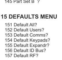
Sub-menu listing for 15 DEFAULTS MENU showing seven items: 151 Default All?, 152 Default Users?, 153 Default Comms?, 154 Default Keypads?, 155 Default Expandr?, 156 Default ID Bus?, and 157 Default RF?.
| Sub-Menu | Description |
|---|---|
| 151 Default All? | Defaults all devices on the system |
| 152 Default Users? | Defaults User and Engineer codes (but not their names, options etc.) |
| 153 Default Comms? | Defaults the dialler and any such communications device |
| 154 Default Keypads? | Defaults keypads |
| 155 Default Expandr? | Defaults expanders |
| 156 Default ID Bus? | Defaults any devices on the point ID bus system |
| 157 Default RF? | Defaults wireless devices |
Used to default the panel and other devices back to their factory settings. There are seven default options to choose from so that different areas of the system can be defaulted without affecting other areas.
Default all? defaults all devices on the system. Then there is Default Users? which defaults the User and Engineer codes (but not their names, options etc.) Default Comms? defaults the dialler and any such communications device. Default Keypads? and Default Expandr? defaults keypads and expanders. Default ID Bus? defaults any devices on the point ID bus system and finally Default RF System? defaults wireless devices.
Please refer to the back of this manual for details of panel default settings.
16 Firmware Update
In the first instance, you need to be connected to SmartLink to update your firmware (i.e your panel's software).
Select Firmware Update, you will then be prompted to key-in the Mfg. Code:------ (Manufacturer's Code). By default it is 4567. Therefore, key-in 4567 followed by YES. You will then be prompted to key-in the User Code:------. When that is done, the display should say Start File Transfer. Next, go to the relevant page in the SW-1070 section of SmartLink and select File Transfer. This starts updating the firmware.
If you have already commissioned your alarm system (e.g. Zone descriptions, timers, devices etc.); this feature DOES NOT affect its configuration.
17 Voice Demo
This feature can be an effective way of introducing the SW-1070 system to end users. Select Voice Demo. When you press YES the Welcome message appears on the display. Press button 1 and the Welcome message is played back on the speaker. Pressing button 2 plays back the carbon monoxide message, CO Alarm. Here is the full list of demonstration messages...
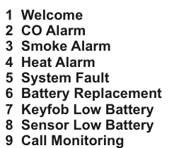
Numbered list of 9 voice demo messages: 1 Welcome, 2 CO Alarm, 3 Smoke Alarm, 4 Heat Alarm, 5 System Fault, 6 Battery Replacement, 7 Keyfob Low Battery, 8 Sensor Low Battery, 9 Call Monitoring.
| Button | Message |
|---|---|
| 1 | Welcome |
| 2 | CO Alarm |
| 3 | Smoke Alarm |
| 4 | Heat Alarm |
| 5 | System Fault |
| 6 | Battery Replacement |
| 7 | Keyfob Low Battery |
| 8 | Sensor Low Battery |
| 9 | Call Monitoring |
18 Remote Service

Sub-menu listing for 18 REMOTE SERVICE showing four items: 181 Report Type, 182 Schedule Date, 183 Test?, and 184 Disable?.
| Sub-Menu | Description |
|---|---|
| 181 Report Type | Select Dial-up or SecureComm communication path |
| 182 Schedule Date | Set up time and date for diagnostics test |
| 183 Test? | Immediately initiate diagnostics test |
| 184 Disable? | Deactivate the Remote Service feature |
This feature allows you to service your system from a distance using SmartLink700. There are two communications paths you can choose from - go to Report Type and select either Dial-up or SecureComm. You will need a DTV dialer for the Dial-up option and communications is via standard landline. For the SecureComm cloud-based service you will need a GSM-SC and communications is via GPRS (or via a broadband router if you use a LAN-Card or a WiFi-Card).
Go into the Schedule Date sub-menu to set-up the time and date for when the system carries out a diagnostics test. The diagnosis is then either sent to your SmartLink700 server if you are using Dial-up or the SecureComm server if you are using SecureComm.
Activating Test ? immediately initiates the diagnostics test and sends the information to either your SmartLink700 server or your SecureComm server as above.
Finally, selecting Disable ? deactivates the Remote Service feature.