Zone Wiring
Your SW-10270 Control Panel comes with a minimum of 10 hardwired zone inputs - Zone 1 to 10.
- By default these are shipped as a non-EOL (end-of-line) input (or Dual EOL 4K7 inputs in the UK).
- The other EOL options are Single EOL, Dual EOL 4K7 and Dual EOL 2K2. See the wiring diagrams below.
- If you have already mapped a wireless detector on to Zone 1 it cannot be used as a hardwired input unless you remove that wireless device and map it on to another zone number instead.
Zone Hardware Menu
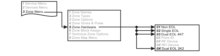
A three-column menu navigation flowchart. First column: 1 Service Menu / 2 Devices Menu / 3 Zone Menu (highlighted). Arrow leads to second column: 1 Zone Names / 2 Zone Types / 3 Zone Options / 4 Zone Gross & Pulse / 5 Zone Hardware (highlighted) / 6 Zone Block Assign / 7 Technical Zone Options / 8 Zone Map Menu. Arrow from 5 Zone Hardware leads to third column: 01 Non EOL / 02 Single EOL / 03 Dual EOL 4K7 / 0X Point ID (greyed) / 0X RF Device (greyed) / 0X RFI Device (greyed) / 0X Dual EOL 2K2.
Menu navigation: 3 Zone Menu → 5 Zone Hardware → Select hardware type
| Option | Hardware Type |
|---|---|
| 01 | Non EOL |
| 02 | Single EOL |
| 03 | Dual EOL 4K7 |
| 0X | Point ID |
| 0X | RF Device |
| 0X | RFI Device |
| 0X | Dual EOL 2K2 |
Standard Non-EOL Wiring
Most commonly used within the industry
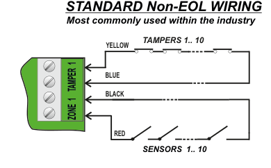
Standard Non-EOL wiring diagram showing a green terminal block labelled ZONE 1 (bottom two terminals) and TAMPER 1 (top two terminals). Four wires connect from the terminal block to the detector(s): YELLOW wire from the top terminal to TAMPERS 1.. 10 (dashed line indicating loop through multiple tamper contacts); BLUE wire from the second terminal; BLACK wire from the third terminal to SENSORS 1.. 10 (dashed line indicating loop through multiple alarm contacts); RED wire from the bottom terminal. No end-of-line resistors are used.
| Wire Colour | Terminal | Connection |
|---|---|---|
| YELLOW | TAMPER 1 (top) | TAMPERS 1.. 10 |
| BLUE | TAMPER 1 (bottom) | Return from tamper loop |
| BLACK | ZONE 1 (top) | SENSORS 1.. 10 |
| RED | ZONE 1 (bottom) | Return from sensor loop |
Single End of Line Wiring
Usually for retrofit in a previous EOL system
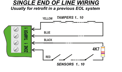
Single End of Line wiring diagram showing a green terminal block labelled ZONE 1 (bottom two terminals) and TAMPER 1 (top two terminals). Four wires connect from the terminal block: YELLOW wire from the top terminal to TAMPERS 1.. 10 (dashed line); BLUE wire from the second terminal; BLACK wire from the third terminal to SENSORS 1.. 10 (dashed line); RED wire from the bottom terminal. A 4K7 resistor is connected across the end of the sensor loop (across SENSORS 1.. 10).
| Wire Colour | Terminal | Connection |
|---|---|---|
| YELLOW | TAMPER 1 (top) | TAMPERS 1.. 10 |
| BLUE | TAMPER 1 (bottom) | Return from tamper loop |
| BLACK | ZONE 1 (top) | SENSORS 1.. 10 |
| RED | ZONE 1 (bottom) | Return from sensor loop |
| Resistor | Value | Position |
|---|---|---|
| End-of-line resistor | 4K7 | Across the sensor loop (at end of line) |
Dual End of Line Wiring 4K7
Single Detector (e.g. PIR with only 4-core cable)
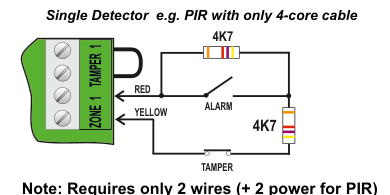
Dual End of Line 4K7 wiring diagram for a single detector (e.g. PIR with only 4-core cable). A green terminal block labelled ZONE 1 (bottom two terminals) and TAMPER 1 (top two terminals). A 4K7 resistor bridges the two TAMPER 1 terminals (top of terminal block). RED wire from the ZONE 1 top terminal connects to the detector's ALARM contact. YELLOW wire from the ZONE 1 bottom terminal connects to the detector. A second 4K7 resistor is connected across the detector's ALARM contacts. The detector's TAMPER contact connects back to the terminal block.
| Wire Colour | Terminal | Connection |
|---|---|---|
| RED | ZONE 1 (top) | Detector ALARM contact |
| YELLOW | ZONE 1 (bottom) | Detector return |
| Resistor | Value | Position |
|---|---|---|
| Tamper resistor | 4K7 | Across TAMPER 1 terminals (at terminal block) |
| Alarm resistor | 4K7 | Across detector ALARM contacts |
Requires only 2 wires (+ 2 power for PIR)
Multiple Detectors (e.g. Inertia Sensors)
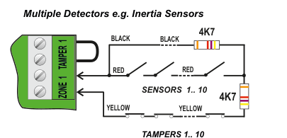
Dual End of Line 4K7 wiring diagram for multiple detectors (e.g. Inertia Sensors). A green terminal block labelled ZONE 1 (bottom two terminals) and TAMPER 1 (top two terminals). BLACK wires from the TAMPER 1 terminals loop through multiple detector tamper contacts, with a 4K7 resistor at the end of the tamper line. RED wires from the ZONE 1 top terminal loop through SENSORS 1.. 10 (alarm contacts in series), with a 4K7 resistor at the end of the sensor line. YELLOW wires from the ZONE 1 bottom terminal loop through TAMPERS 1.. 10 (dashed line).
| Wire Colour | Terminal | Connection |
|---|---|---|
| BLACK | TAMPER 1 (both) | Loop through detector tamper contacts |
| RED | ZONE 1 (top) | SENSORS 1.. 10 (alarm contacts in series) |
| YELLOW | ZONE 1 (bottom) | TAMPERS 1.. 10 |
| Resistor | Value | Position |
|---|---|---|
| Tamper end-of-line resistor | 4K7 | End of tamper line (across BLACK wires) |
| Alarm end-of-line resistor | 4K7 | End of sensor line (across SENSORS 1.. 10) |
Additional return wire required
Dual End of Line Wiring 2K2
Single Detector (e.g. PIR with only 4-core cable)
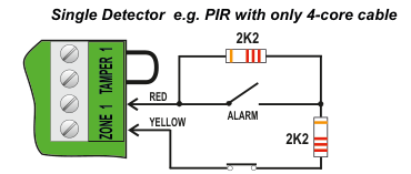
Dual End of Line 2K2 wiring diagram for a single detector (e.g. PIR with only 4-core cable). A green terminal block labelled ZONE 1 (bottom two terminals) and TAMPER 1 (top two terminals). A 2K2 resistor bridges the two TAMPER 1 terminals (top of terminal block). RED wire from the ZONE 1 top terminal connects to the detector's ALARM contact. YELLOW wire from the ZONE 1 bottom terminal connects to the detector. A second 2K2 resistor is connected across the detector's ALARM contacts. The detector's TAMPER contact connects back to the terminal block.
| Wire Colour | Terminal | Connection |
|---|---|---|
| RED | ZONE 1 (top) | Detector ALARM contact |
| YELLOW | ZONE 1 (bottom) | Detector return |
| Resistor | Value | Position |
|---|---|---|
| Tamper resistor | 2K2 | Across TAMPER 1 terminals (at terminal block) |
| Alarm resistor | 2K2 | Across detector ALARM contacts |
Requires only 2 wires (+ 2 power for PIR)
Multiple Detectors (e.g. Inertia Sensors)
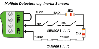
Dual End of Line 2K2 wiring diagram for multiple detectors (e.g. Inertia Sensors). A green terminal block labelled ZONE 1 (bottom two terminals) and TAMPER 1 (top two terminals). BLACK wires from the TAMPER 1 terminals loop through multiple detector tamper contacts, with a 2K2 resistor at the end of the tamper line. RED wires from the ZONE 1 top terminal loop through SENSORS 1.. 10 (alarm contacts in series), with a 2K2 resistor at the end of the sensor line. YELLOW wires from the ZONE 1 bottom terminal loop through TAMPERS 1.. 10 (dashed line).
| Wire Colour | Terminal | Connection |
|---|---|---|
| BLACK | TAMPER 1 (both) | Loop through detector tamper contacts |
| RED | ZONE 1 (top) | SENSORS 1.. 10 (alarm contacts in series) |
| YELLOW | ZONE 1 (bottom) | TAMPERS 1.. 10 |
| Resistor | Value | Position |
|---|---|---|
| Tamper end-of-line resistor | 2K2 | End of tamper line (across BLACK wires) |
| Alarm end-of-line resistor | 2K2 | End of sensor line (across SENSORS 1.. 10) |
Additional return wire required