RF-RKP (Wireless Remote Keypad)
Hardware
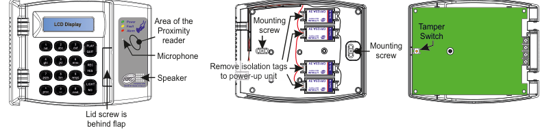
Three views of the RF-RKP device. Left (front view): A wall-mounted keypad unit showing an LCD Display at the top, three status LEDs on the upper-right labelled Power, Fault, and Alarm, a sticker reading "Complies with EN 50131 Grade 2 Class II", and a numeric keypad with buttons arranged in four rows: Row 1: 1(txt), 2(abc), 3(def), PLAY, QUIT; Row 2: 4(ghi), 5(jkl), 6(mno), REC/YES; Row 3: 7(pqrs), 8(tuv), 9(wxyz), LIGHT; Row 4: prev/*, 0, #/next, NO. To the right of the keypad is the Area of the Proximity reader, below it a Microphone, and below that a Speaker. At the bottom-centre: "Lid screw is behind flap". Centre (battery compartment): The back of the unit with lid open showing four CR123A batteries in holders, two Mounting screws (top-left and bottom-right), and a label "Remove isolation tags to power-up unit". Right (PCB view): A green PCB with a Tamper Switch labelled at the top-right, and a Mounting screw at the right side.
| Component | Description |
|---|---|
| LCD Display | Two-line LCD screen (top of keypad) |
| Status LEDs | Power, Fault, Alarm indicators (upper-right of keypad) |
| Numeric Keypad | Buttons 0–9, */prev, #/next, PLAY, QUIT, REC/YES, LIGHT, NO |
| Proximity Reader | Built-in proximity reader area (right side of front panel) |
| Microphone | For audio memo-pad (right side, below proximity reader) |
| Speaker | For audible messages and buzzer (right side, below microphone) |
| Lid Screw | Behind flap at bottom of front panel |
| Battery Compartment | 4x CR123A 3V Lithium batteries (centre, behind lid) |
| Tamper Switch | Detects case opening (on green PCB) |
| Mounting Screws | For wall mounting (two locations on case back) |
Key Features
- >400m Line-of-sight Radio Range
- Battery Life > 3 years (based on 2 arm/disarm cycles per day)
- Comes with Proximity reader as standard
- Can be powered from a permanent 12Vdc supply (this allows keypad to be always 'awake' and for longer LED back-lighting)
- 2 x RF-RKP per SW-10270 system
- Entry/Exit buzzer
- Audio memo-pad
- Large library of audible messages
- Compliant with EN 50131-3 Grade 2 Class II
- Also, BS 8243
Add & ID on to the System
RF-KEYPAD can connect to RF-Expander

A three-column menu navigation flowchart. First column: 1 Service Menu / 2 Devices Menu / 3 Zone Menu. Arrow leads to second column: 1 RF Devices Menu / 2 Wired Devices Menu. Arrow leads to third column: 1 Add & ID RF Devices / 2 Locate RF Devices / 3 Remove RF Devices.
- To put an RF-RKP on to a SecureWave system go into engineer mode. Select the Devices Menu. Then RF Devs Menu. Next, select the Add & Id RF Devs option.
The sub-menu offers device types including RF Keypad:

A three-column sub-menu flowchart. First column: 1 Add & ID RF Devices / 2 Locate RF Devices / 3 Remove RF Devices. Arrow leads to second column: 4 Add&Id:RF SABB / 5 Add&Id:RF Wand / 6 Add&Id:RF Keypad (highlighted in bold). Arrow from 6 Add&Id:RF Keypad leads to Scanning RF Devs in the third column.
4 Add&Id:RF SABB— add and identify RF SABB devices5 Add&Id:RF Wand— add and identify RF Wand devices6 Add&Id:RF Keypad— add and identify the RF-RKP
The system displays Devs Found - 000 when it starts scanning and as it finds its first device the display will change to Devs Found - 001. When the system has found all its devices (you can only have two RF-RKP per installation*) press PLAY/QUIT to stop the scanning process.
- Close the tamper switches in sequence. You will hear an audible indication as each device is identified into the system.
The RF-Echo can have a delayed reaction.
RF Device Options (Programmable Settings)

A three-column navigation flowchart. First column: 1 Service Menu / 2 Devices Menu / 3 Zone Menu. Arrow to second column: 1 RF Devices Menu / 2 Wired Devices Menu. Arrow to third column: 1 Add & ID RF Devices / 2 Locate RF Devices / 3 Remove RF Devices / 4 RF Devs Options (highlighted with arrow).

A two-column sub-menu flowchart. First column: 1 Add & ID RF Devices / 2 Locate RF Devices / 3 Remove RF Devices / 4 RF Devs Options (highlighted). Arrow leads to second column: 4 RF SABB Opts / 5 RF Wand Opts / 6 RF Keypad Opts (highlighted with arrow).
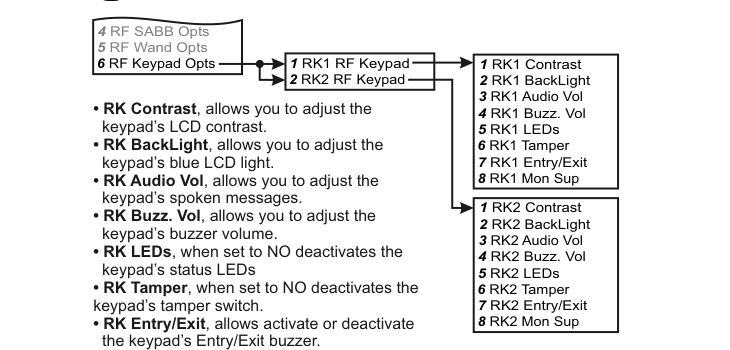
A three-column sub-menu flowchart with two branches. First column: 4 RF SABB Opts / 5 RF Wand Opts / 6 RF Keypad Opts (highlighted). Arrow leads to centre column: 1 RK1 RF Keypad / 2 RK2 RF Keypad. From 1 RK1 RF Keypad, arrow leads to top-right list: 1 RK1 Contrast / 2 RK1 BackLight / 3 RK1 Audio Vol / 4 RK1 Buzz. Vol / 5 RK1 LEDs / 6 RK1 Tamper / 7 RK1 Entry/Exit / 8 RK1 Mon Sup. From 2 RK2 RF Keypad, arrow leads to bottom-right list: 1 RK2 Contrast / 2 RK2 BackLight / 3 RK2 Audio Vol / 4 RK2 Buzz. Vol / 5 RK2 LEDs / 6 RK2 Tamper / 7 RK2 Entry/Exit / 8 RK2 Mon Sup. Bullet-point descriptions in the centre explain each setting: RK Contrast allows you to adjust the keypad's LCD contrast; RK BackLight allows you to adjust the keypad's blue LCD light; RK Audio Vol allows you to adjust the keypad's spoken messages; RK Buzz. Vol allows you to adjust the keypad's buzzer volume; RK LEDs when set to NO deactivates the keypad's status LEDs; RK Tamper when set to NO deactivates the keypad's tamper switch; RK Entry/Exit allows activate or deactivate the keypad's Entry/Exit buzzer.
The RF-RKP's programmable options can be accessed as follows:
Menu navigation: 1 Service Menu → 2 Devices Menu → 1 RF Devices Menu → 4 RF Devs Options
Go to the Devices Menu, then RF Devs Menu. Next select the RF Devs Options. Scroll to RF Keypad Opts.
Sub-menu path: 4 RF Devs Options → 6 RF Keypad Opts → Select keypad (RK1, RK2)
When you select the RF Keypad Opts menu, you will see RK1 RF Keypad. Select this or scroll to the other keypad by pressing #/next.
RK Contrast (LCD Contrast)
RK Contrast allows you to adjust the keypad's LCD contrast.
RK BackLight (LCD Backlight)
RK BackLight allows you to adjust the keypad's blue LCD light.
RK Audio Vol (Audio Volume)
RK Audio Vol allows you to adjust the keypad's spoken messages.
RK Buzz. Vol (Buzzer Volume)
RK Buzz. Vol allows you to adjust the keypad's buzzer volume.
RK LEDs (Status LEDs)
RK LEDs, when set to NO, deactivates the keypad's status LEDs.
| Setting | Description |
|---|---|
| RK LEDs YES | Status LEDs active |
| RK LEDs NO | Status LEDs deactivated |
RK Tamper (Tamper Switch)
RK Tamper, when set to NO, deactivates the keypad's tamper switch.
| Setting | Description |
|---|---|
| RK Tamper YES | Tamper switch active |
| RK Tamper NO | Tamper switch deactivated |
RK Entry/Exit (Entry/Exit Buzzer)
RK Entry/Exit allows you to activate or deactivate the keypad's Entry/Exit buzzer.
| Setting | Description |
|---|---|
| RK Entry/Exit YES | Entry/Exit buzzer active |
| RK Entry/Exit NO | Entry/Exit buzzer deactivated |
RK Mon Sup (Monitored Supervisory)
RK Mon Sup (Monitored Supervisory signal) is defaulted to YES. When the device is 'lost' for >120 minutes a supervisory alarm is flagged by the panel. This can be turned off by selecting NO. However, we recommend that this feature is left as YES.
| Setting | Description |
|---|---|
| RK Mon Sup YES | Supervisory alarm enabled (default) |
| RK Mon Sup NO | Supervisory alarm disabled |
We recommend that this feature is left as YES.
In RF System Options you can globally adjust the supervisory time by going to the Sup. Time (supervisory Time) menu.
Recording the site name via the RF-RKP's microphone is not available.
If there are no wired or RF keypads already assigned to the system and you then power-up an RF-RKP within range, it will automatically attach itself to the system. It will detach itself if it is out of range for 10 minutes or there are no key-presses for 1 hour. To stop it from detaching, it will need to be Added & ID'ed.
If there has already been a wired or RF keypad assigned to the system you can still get an RF-RKP to automatically attach so long as you are in Engineer mode and the tamper switch is open. Again, to stop it from detaching, it will need to be Added & ID'ed.
Locate RF Devices

A three-column menu navigation flowchart. First column: 1 RF Devices Menu / 2 Wired Devices Menu. Arrow to second column: 1 Add & ID RF Devices / 2 Locate RF Devices (highlighted in bold) / 3 Remove RF Devices. Arrow to third column: 4 Locate:RF SABB / 5 Locate:RF Wand / 6 Locate:RF Keypad (highlighted in bold with arrow).
Menu path: 2 Devices Menu → 1 RF Devices Menu → 2 Locate RF Devices → 6 Locate:RF Keypad
In the Locate:RF Keypad menu you will observe the three LEDs on the front of the RF-RKP in question flash on and off every second when you select it.
Go to the Devices Menu in engineer mode and follow the menu path above.
Remove RF Devices

A three-column menu navigation flowchart. First column: 1 RF Devices Menu / 2 Wired Devices Menu. Arrow to second column: 1 Add & ID RF Devices / 2 Locate RF Devices / 3 Remove RF Devices (highlighted in bold). Arrow to third column: 4 Remove:RF SABB / 5 Remove:RF Wand / 6 Remove:RF Keypad (highlighted in bold with arrow).
Menu path: 2 Devices Menu → 1 RF Devices Menu → 3 Remove RF Devices → 6 Remove:RF Keypad
- To remove an RF-RKP go to the Remove:RF Keypad menu in engineer mode and follow the menu path above.
- You will automatically be brought to RF-RKP 1.
- Go to the RF-RKP you want to remove and press REC/YES.
- Follow the prompts on the display.
Specifications
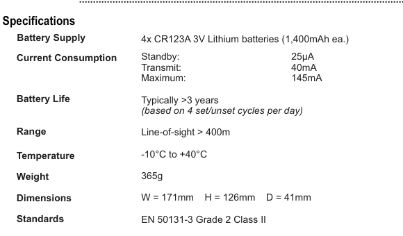
A two-column specifications table with parameter names in bold on the left and values on the right. Lists: Battery Supply — 4x CR123A 3V Lithium batteries (1,400mAh ea.); Current Consumption — Standby: 25µA, Transmit: 40mA, Maximum: 145mA; Battery Life — Typically >3 years (based on 4 set/unset cycles per day); Range — Line-of-sight > 400m; Temperature — -10°C to +40°C; Weight — 365g; Dimensions — W=171mm H=126mm D=41mm; Standards — EN 50131-3 Grade 2 Class II.
| Parameter | Value |
|---|---|
| Battery Supply | 4x CR123A 3V Lithium batteries (1,400mAh ea.) |
| Current Consumption | Standby: 25µA / Transmit: 40mA / Maximum: 145mA |
| Battery Life | Typically >3 years (based on 4 set/unset cycles per day) |
| Range | Line-of-sight > 400m |
| Temperature | -10°C to +40°C |
| Weight | 365g |
| Dimensions | W=171mm H=126mm D=41mm |
| Standards | EN 50131-3 Grade 2 Class II |
Permanent 12Vdc Supply
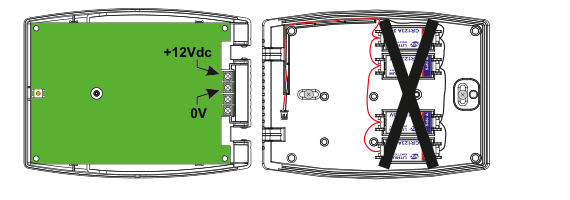
An internal view of the RF-RKP with the lid open, showing two compartments. Left side (PCB): A green PCB with two arrows pointing to wiring terminals labelled +12Vdc (top) and 0V (bottom). Right side (battery compartment): The four-battery CR123A holder with a large X drawn across it, indicating the battery pack must NOT be connected when using a permanent 12Vdc supply.
When wiring a permanent 12Vdc supply to the RF-RKP please ensure that the battery pack (the one with the 4 Lithium batteries) IS NOT CONNECTED.