System Hardware: Remote Keypad
Keypad Front View
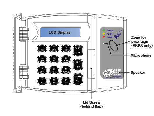
Front view of the remote keypad unit. The keypad is a rectangular wall-mounted device with a grey/silver housing. The following components are labeled, from top to bottom and left to right:
Top section:
- LCD Display — A backlit LCD screen across the top of the keypad face, used for status messages and menu navigation.
Right-side panel (grey area beside the main keypad face):
- Status LEDs — Three indicator LEDs at the top-right:
- Power (green LED)
- Fault (yellow/amber LED)
- Alarm (red LED)
- Zone for prox tags (RKPX only) — An area on the right-side panel where proximity tags can be presented. This feature is only available on the RKPX model.
- Microphone — Located on the right-side panel, below the prox tag zone.
- Speaker — Located on the right-side panel, below the microphone area. An HKC logo and the EN 50131 compliance badge are visible nearby.
- Complies with EN 50131 Grade 2 Class II — Compliance badge printed on the right-side panel.
Button layout (4 columns x 4 rows of main keys, plus function keys):
| Column 1 | Column 2 | Column 3 | Column 4 |
|---|---|---|---|
| 1 (txt) | 2 (abc) | 3 (def) | PLAY / QUIT |
| 4 (ghi) | 5 (jkl) | 6 (mno) | REC / YES |
| 7 (pqrs) | 8 (tuv) | 9 (wxyz) | LIGHT / NO |
| * / prev | 0 | # / next |
Each number key (1-9) has associated letters printed beneath it for text entry. The * key doubles as prev (previous), and the # key doubles as next. The right-column function keys each serve dual purposes: PLAY/QUIT, REC/YES, and LIGHT/NO.
Bottom:
- Lid Screw (behind flap) — A screw securing the keypad lid, located behind a flip-down flap at the bottom-centre of the keypad.
Keypad Rear / Internal View
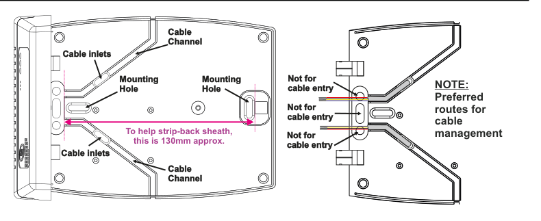
Rear and internal view of the remote keypad, showing two halves of the opened case side by side.
Left half — Back of the keypad base (wall-mounting plate):
- Cable inlets (x2) — Two cable entry points located on the top-left and bottom-left edges of the base plate, where cables can be routed into the keypad.
- Mounting Hole (x2) — Two screw mounting holes for wall-fixing, one in the upper-left area and one in the centre-right area of the base plate.
- Cable Channel (x2) — Two cable routing channels moulded into the base plate, one at the top and one at the bottom, for managing cable runs neatly within the enclosure.
- To help strip-back sheath, this is 130mm approx. — A pink reference line spanning the width of the base plate to help the installer gauge the correct sheath strip-back length of 130mm.
Right half — Inside of the keypad lid (cable routing cover):
- Not for cable entry (x3) — Three locations on the hinged lid are marked "Not for cable entry," indicating that these openings must not be used to route cables into the keypad.
- NOTE: Preferred routes for cable management — A note indicating the preferred cable paths through the cable channels in the base plate rather than through the lid openings.
Cable Preparation

Cable preparation diagram for the remote keypad. A length of multi-core cable (with white outer sheath and four coloured inner cores: yellow, red, black, and purple/blue) is shown with two measurements:
- 100mm - 130mm — The length of outer sheath that should be stripped back from the end of the cable, indicated by a double-headed arrow beneath the exposed cores.
- Also, strip back about 5mm from each core — The amount of insulation to strip from each individual inner core at the cable end.
The accompanying note text reads: "NOTE: When preparing the cable for the keypad, we recommend that the outer sheath be stripped back by 100 - 130mm approx. This will allow the keypad cover to open fully."
When preparing the cable for the keypad, we recommend that the outer sheath be stripped back by 100 - 130mm approx. This will allow the keypad cover to open fully.
Also, strip back about 5mm from each core.
The RKP's tamper switch is located here (on the internal rear of the keypad — see wiring diagram below).
Wiring
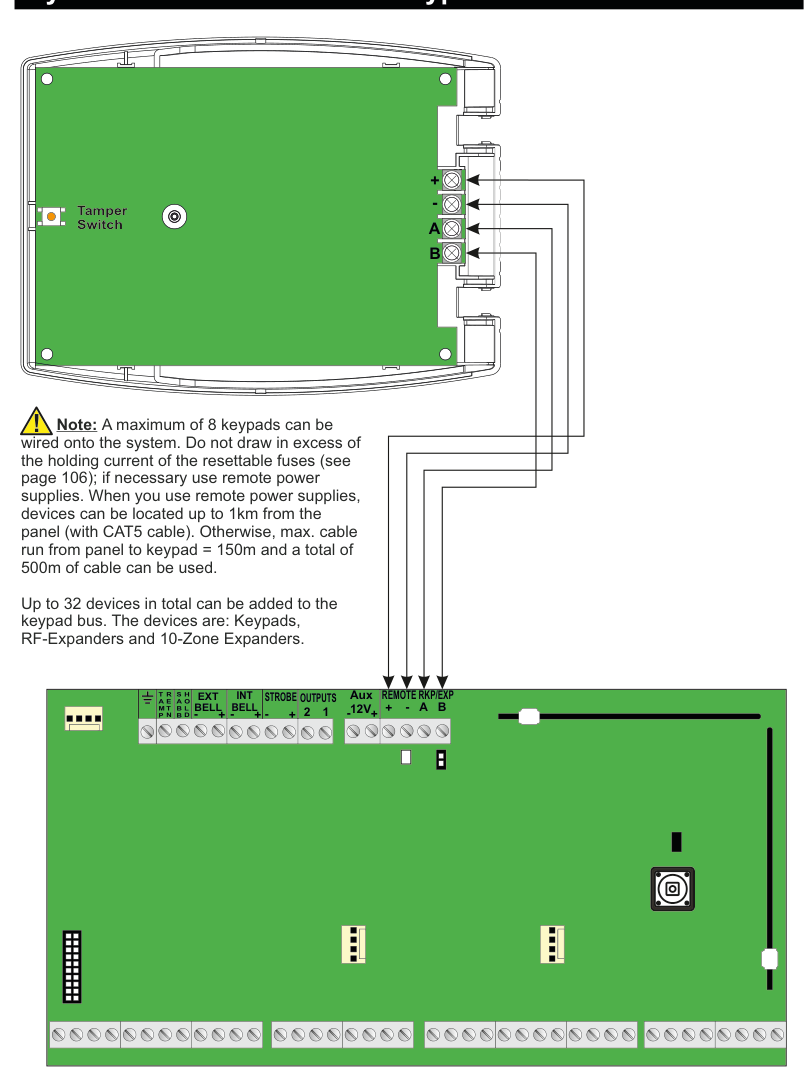
Full wiring diagram for the remote keypad, shown in two connected parts:
Top — Rear of keypad (green PCB and case):
- Tamper Switch — Located on the left side of the keypad rear PCB, shown as a small orange/red and white rectangular component.
- Four terminal screw connections on the right side of the keypad, with arrows indicating where wires connect. From top to bottom:
- + (positive power)
- - (negative/ground power)
- A (data line A)
- B (data line B)
Bottom — Main panel circuit board (green PCB):
- The main panel terminal strip is shown along the top edge of the panel board, with the following terminal groups labeled from left to right:
- TAMP / SABB / RETN / HOLD (vertically labeled on the far-left connector block)
- EXT BELL (+, -)
- INT BELL (+, -)
- STROBE (+, -)
- OUTPUTS (+, 2, 1)
- Aux 12V (+, -)
- REMOTE RKP/EXP (+, -, A, B)
Wiring connections (four wires from keypad to panel): Four wires run from the keypad terminals down to the panel's REMOTE RKP/EXP terminal group:
- Keypad + connects to panel REMOTE RKP/EXP +
- Keypad - connects to panel REMOTE RKP/EXP -
- Keypad A connects to panel REMOTE RKP/EXP A
- Keypad B connects to panel REMOTE RKP/EXP B
The arrows on the diagram show the direction of wiring from the panel terminals up to the corresponding keypad terminals.
Wiring Notes
A maximum of 8 keypads can be wired onto the system. Do not draw in excess of the holding current of the resettable fuses (see page 106); if necessary use remote power supplies. When you use remote power supplies, devices can be located up to 1km from the panel (with CAT5 cable). Otherwise, max. cable run from panel to keypad = 150m and a total of 500m of cable can be used.
Up to 32 devices in total can be added to the keypad bus. The devices are: Keypads, RF-Expanders and 10-Zone Expanders.