RF-Keyfob (Wireless Keyfob)
Hardware
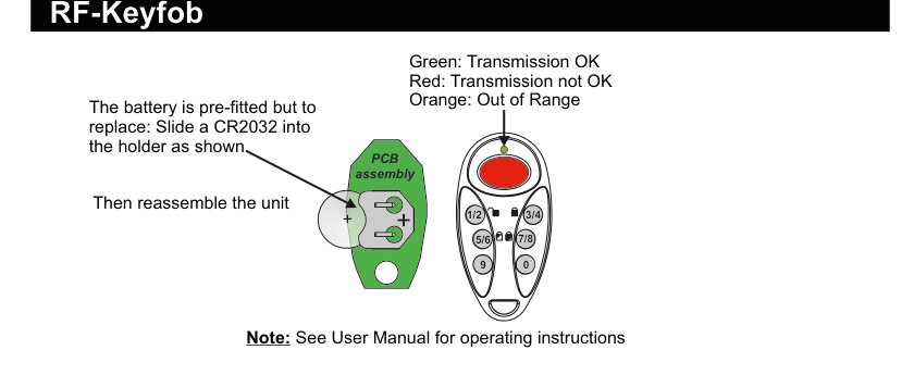
Two views of the RF-Keyfob device. PCB assembly (left): a circular green circuit board with CR2032 battery holder showing polarity markings (+ and −), with text "The battery is pre-fitted but to replace: Slide a CR2032 into the holder as shown. Then reassemble the unit." Front view (right): a rounded keyfob unit with a large red Duress button at the top, a green LED indicator dot, and six numbered buttons arranged in pairs: 1/2 (top-left), 3/4 (top-right), 5/6 (middle-left), 7/8 (middle-right), 9 (bottom-left), and 0 (bottom-right). LED colour indicators are listed: Green = Transmission OK, Red = Transmission not OK, Orange = Out of Range.
See User Manual for operating instructions.
Battery: CR2032 (pre-fitted). To replace, slide the battery into the holder observing polarity, then reassemble the unit.
LED Indicators
| LED Colour | Meaning |
|---|---|
| Green | Transmission OK |
| Red | Transmission not OK |
| Orange | Out of Range |
Button Layout
| Button | Function |
|---|---|
| 1/2 (top-left) | Press once to Unset |
| 3/4 (top-right) | Press once to Full-set |
| 5/6 (middle-left) | Press once for Part-set A |
| 7/8 (middle-right) | Press once for Part-set B |
| 9 (bottom-left) | Toggle Lights On/Off (if applicable) |
| 0 (bottom-right) | Used in CodeUnset mode |
| Red button (large, top) | Press and hold for 2 seconds or more for Duress |
Add & ID on to the System
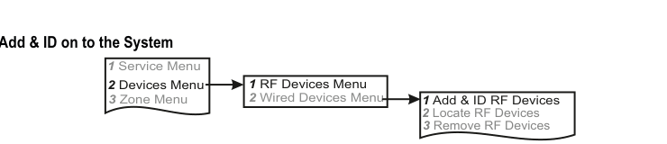
A three-column menu navigation flowchart. First column: 1 Service Menu / 2 Devices Menu / 3 Zone Menu. Arrow leads to second column: 1 RF Devices Menu / 2 Wired Devices Menu. Arrow leads to third column: 1 Add & ID RF Devices / 2 Locate RF Devices / 3 Remove RF Devices.
- To put an RF-Keyfob on to a SecureWave system go into engineer mode. Select the Devices Menu, then RF Devs Menu. Next, select the Add & Id RF Devs option.
- Next, add and identify the device(s) as an RF Keyfob.
The sub-menu offers three device types:
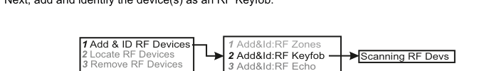
A three-column sub-menu flowchart. First column: 1 Add & ID RF Devices / 2 Locate RF Devices / 3 Remove RF Devices. Arrow leads to second column: 1 Add&Id:RF Zones / 2 Add&Id:RF Keyfob (highlighted) / 3 Add&Id:RF Echo. Arrow from 2 Add&Id:RF Keyfob leads to Scanning RF Devs in the third column.
1 Add&Id: RF Zones— add and identify RF zone devices2 Add&Id: RF Keyfob— add and identify the RF-Keyfob3 Add&Id: RF Echo— add and identify RF Echo devices
The system displays Devs Found - 000 when it starts scanning.
- Press any button on the RF-Keyfob to wake it up. This action does not ID it into the system.
- If you have a number of RF-Keyfobs you can wake them up at this stage too.
- As the system finds its first device the display will change to Devs Found - 001. When the system has found all its devices, press PLAY/QUIT.
- You will have to press any button on the RF-Keyfob again in order to add and ID it into the system.
- At this stage you can associate a keyfob with a particular end user, i.e. U01 Keyfob 1, U02 Keyfob 2, etc.
- As the RF-Keyfob(s) are added to the system, you will hear an audible indication.
The RF-Echo can have a delayed reaction.
Only 1 RF-Keyfob per User.
RF Device Options (Programmable Settings)
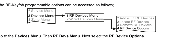
A three-column navigation flowchart. First column: 1 Service Menu / 2 Devices Menu / 3 Zone Menu. Arrow to second column: 1 RF Devices Menu / 2 Wired Devices Menu. Arrow to third column: 1 Add & ID RF Devices / 2 Locate RF Devices / 3 Remove RF Devices / 4 RF Device Options (highlighted).
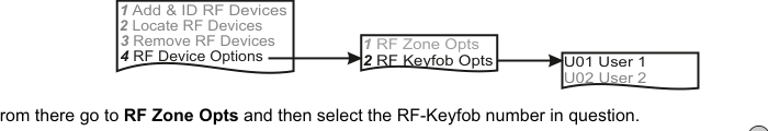
A three-column sub-menu flowchart. First column: 1 Add & ID RF Devices / 2 Locate RF Devices / 3 Remove RF Devices / 4 RF Device Options. Arrow to second column: 1 RF Zone Opts / 2 RF Keyfob Opts (highlighted). Arrow to third column showing user assignments: U01 User 1 / U02 User 2.
The RF-Keyfob's programmable options can be accessed as follows:
Menu navigation: 1 Service Menu → 2 Devices Menu → 1 RF Devices Menu → 4 RF Device Options
Go to the Devices Menu, then RF Devs Menu. Next select the RF Device Options.
From there go to RF Keyfob Opts and then select the RF-Keyfob number in question.
Sub-menu path: 4 RF Device Options → 2 RF Keyfob Opts → Select user (U01, U02, etc.)
CodeUnset
By default, an RF-Keyfob Arms and Unsets the system with the single push of a button — button 1/2 to Unset and button 3/4 to fully Arm. For increased security you may want to change this so that you have to key-in a User Code.
For example, if you want to key-in User Code 1 to Unset the system, change U01 CodeUnset NO to U01 CodeUnset YES.
| Setting | Description |
|---|---|
| CodeUnset NO | Arm/Unset with a single button press (default) |
| CodeUnset YES | Requires User Code entry to Unset |
Duress
Pressing the big red button on the RF-Keyfob activates a Duress signal to the monitoring station. Changing Duress from YES to NO turns off this feature.
| Setting | Description |
|---|---|
| Duress YES | Duress signal enabled (default) |
| Duress NO | Duress signal disabled |
DuresBell
By default this feature is active but there is no siren activation during a Duress event. If you want the siren to activate during a Duress event, change DuresBell NO to DuresBell YES.
| Setting | Description |
|---|---|
| DuresBell NO | No siren during Duress (default) |
| DuresBell YES | Siren activates during Duress |
DuresDly (Duress Delay)
To avoid accidental Duress activations, the red button needs to be held for approximately 2 seconds. To make this more sensitive, go to DuresDly and change the number 20 to a smaller number. To make it less sensitive, increase the number. The range is 4 to 99 (i.e. 0.4 sec to 9.9 sec).
| Setting | Description |
|---|---|
| DuresDly 20 | 2.0 second hold required (default) |
| DuresDly 4–99 | 0.4 sec to 9.9 sec hold (adjustable range) |
ArmSquawk
Changing ArmSquawk NO to ArmSquawk YES will mean that the internal siren and strobe on the external siren will activate for about 2 seconds when the system is fully Armed with an RF-Keyfob (at the end of the exit time).
| Setting | Description |
|---|---|
| ArmSquawk NO | No audible confirmation when arming (default) |
| ArmSquawk YES | Siren/strobe activates for ~2 seconds on Arm |
If there is no squawk the system may have a condition that prevents arming. As a matter of good practice, set to ArmSquawk YES when using an RF-Keyfob.
The buttons on the RF-Keyfob have to be very deliberately pressed. Every time you press a button, make sure the green LED flashes. When it does, it means that the panel has successfully received the key-press. This should be particularly noted for systems where there will be a high instance of key-pressing, for instance in systems where CodeUnset is set to YES.
Locate RF Devices
To locate an RF-Keyfob go to the Devices Menu in engineer mode and follow the menu path below.
Menu path: 2 Devices Menu → 1 RF Devices Menu → 2 Locate RF Devices
Remove RF Devices
Menu path: 2 Devices Menu → 1 RF Devices Menu → 3 Remove RF Devices
- To remove an RF-Keyfob go to the Devices Menu in engineer mode and follow the menu path above.
RF-Keyfob in Quick Key Mode
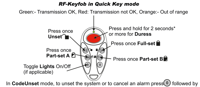
A labelled diagram of the RF-Keyfob showing button functions. At the top: "RF-Keyfob in Quick Key mode" heading with LED colour legend: "Green: Transmission OK, Red: Transmission not OK, Orange: Out of range". The keyfob is shown with all buttons labelled: top-left 1/2 = "Press once Unset" (with padlock-open icon), top centre large red button = "Press and hold for 2 seconds or more for Duress", top-right 3/4 = "Press once Full-set" (with padlock-closed icon), middle-left 5/6 = "Press once Part-set A" (with padlock icon), middle-right 7/8 = "Press once Part-set B" (with padlock icon), bottom-left 9 = "Toggle Lights On/Off (if applicable)", bottom-right 0 = used for CodeUnset mode. At the bottom: "In CodeUnset mode, to unset the system or to cancel an alarm press 0 followed by User Code."
| Button | Action |
|---|---|
| 1/2 | Press once to Unset |
| 3/4 | Press once to Full-set |
| 5/6 | Press once for Part-set A |
| 7/8 | Press once for Part-set B |
| 9 | Toggle Lights On/Off (if applicable) |
| 0 | Press in CodeUnset mode (followed by User Code) |
| Red button | Press and hold for 2 seconds or more for Duress |
In CodeUnset mode, to unset the system or to cancel an alarm press 0 followed by User Code.