Status LEDs
Dialler Status LED
The Dialler Status LED is located on the Mark II DTV module board.
Call Progress Status Indication LED
| Status | LED Colour |
|---|---|
| Wait for Dial Tone | Red |
| Sending Message / On-line | Orange - turning off as packets are sent |
| Successful Transmission | Green for one second after transmission |
| No Kissoff* | Red for one second after transmission |
* Applicable to Central Station transmission
Line Monitor Status Indication LED
| Status | LED Indication |
|---|---|
| Line OK | One red flash |
| Phone Off Hook | Two red flashes |
| Line Dead | Three red flashes |
Troubleshooting
-
The Digi Modem line status LED doesn't flash but stays red — The Digi Modem is trying to make a call but has yet to detect a dial tone. Go to the "Dial Tone Options" in the "Phone Options Menu" and select NO beside the appropriate number.
-
The Digi Modem line status LED changes from red to orange — The Digi Modem is communicating with the Central Station, SmartLink 7 or the Text Messaging server. No action is required.
-
The Digi Modem line status LED changes to green for 1 second — The transmission has been successful. Apart from possibly contacting the Central Station for confirmation, no action is required.
-
If the Digi Modem line status LED changes to red for 1 second — The transmission has not been successful. Try again or contact your Central Station Company.
-
3 red flashes on the Digi Modem line status LED — The Digi Modem assumes that the phone line is dead. Check the voltage across the A & B terminal. It should be between 40 and 58Vdc. Ensure that the in-coming phone line is wired to terminals A & B.
-
2 red flashes on the Digi Modem line status LED — The Digi Modem assumes that the telephone handset wired into terminals C & D is off-hook. The customer is probably making a phone call on their handset in which case no action is required.
-
1 red flash on the Digi Modem line status LED — The phone line to the Digi Modem is ok. No action is required.
GSM-Q Status LED
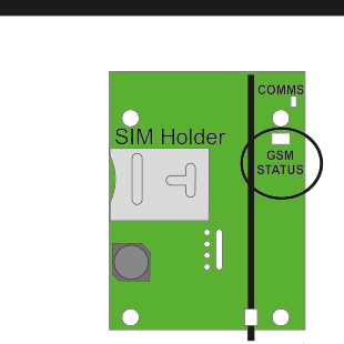
Hardware diagram of the GSM-Q module (green circuit board). Visible components:
- SIM Holder: Located on the left side of the board, with a slot for the SIM card.
- COMMS LED: Located in the top-right corner of the board, labeled "COMMS".
- GSM STATUS LED: Located on the right side of the board, circled and labeled "GSM STATUS".
- The board also shows various connectors and mounting holes.
Idle State
| LED Indication | Meaning |
|---|---|
| 3 Short Red Flashes | Not registered to GSM network |
| 1 Green Flash | 20% GSM Signal Strength |
| 2 Green Flashes | 40% GSM Signal Strength |
| .. | .. |
| 5 Green Flashes | 100% GSM Signal Strength |
Active State
Orange during active state then at end...
- Green Flash = GOOD (i.e kiss-off)
- Red Flash = BAD (No kiss-off or other fail reason)
Disabled State
RED on constant.
To save power, LED light level is deliberately low.
COMMS LED flashes in unison with serial port data on panel.
GSM-WiFi Status LED

Hardware diagram of the GSM-WiFi module (green circuit board). Visible components:
- GSM STATUS LED: Located on the upper-left area of the board, labeled "GSM STATUS".
- WiFi STATUS LED: Located on the lower-left area of the board, labeled "WiFi STATUS".
- The board also shows various connectors, mounting holes, and a vertical antenna strip on the right side.
GSM and WiFi STATUS LEDs
Idle State
| LED Indication | Meaning |
|---|---|
| 3 Short Red Flashes | Not registered to GSM network / WiFi Router |
| 1 Green Flash | 20% GSM / WiFi Signal Strength |
| 2 Green Flashes | 40% GSM / WiFi Signal Strength |
| .. | .. |
| 5 Green Flashes | 100% GSM / WiFi Signal Strength |
Active State
Orange during active state then at end...
- Green Flash = Sucess
- Red Flash = Communications Fault
Disabled State
RED on constant.