RF-PA (Panic Attack Button)
Hardware
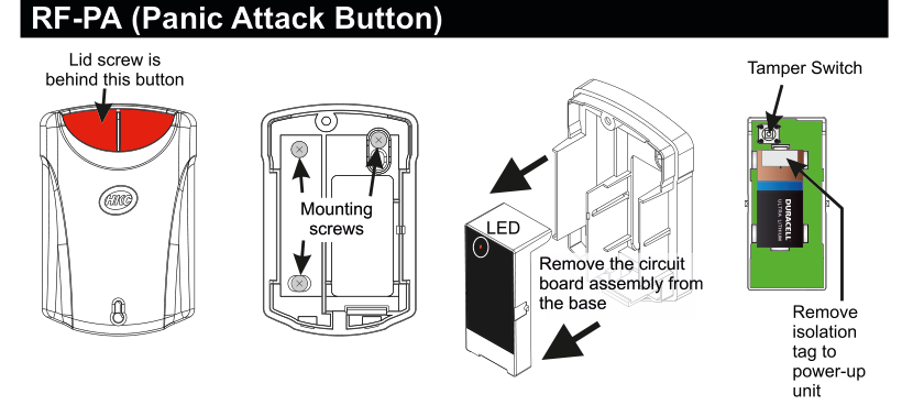
Four views of the RF-PA device. Far left: front view of the closed unit showing a red button at the top with the HKC logo below it, and a label "Lid screw is behind this button" with an arrow pointing to the red button area. Centre-left: rear/internal view of the base showing two Mounting screws (labelled with arrows). Centre: the circuit board assembly being removed from the base, with a label "Remove the circuit board assembly from the base" and arrows indicating the extraction direction; an LED is labelled on the side of the circuit board. Far right: internal view of the circuit board with a Duracell Ultra Lithium battery installed; a Tamper Switch is labelled at the top with an arrow, and "Remove isolation tag to power-up unit" is labelled at the bottom with an arrow pointing to the battery isolator tag.
| Component | Description |
|---|---|
| Red Button | Dual push button on the front of the unit (lid screw is behind this button) |
| Mounting Screws | For wall mounting (visible on the rear of the base) |
| LED | Status indicator (on the side of the circuit board assembly) |
| Tamper Switch | Detects case opening (top of internal PCB) |
| Battery Isolator | Remove isolation tag to power-up unit |
Key Features
- Recommend that battery is changed every 3 years
- >300m Line-of-sight Radio Range
- Dual push button operation
- Compliant with EN 50131-1 Grade 2 Class II
- Also, BS 8243 (Confirmed Hold-up)
Add & ID on to the System

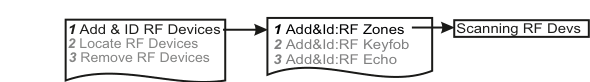
A three-column menu navigation flowchart. First column: 1 Service Menu / 2 Devices Menu / 3 Zone Menu. Arrow leads to second column: 1 RF Devices Menu / 2 Wired Devices Menu. Arrow leads to third column: 1 Add & ID RF Devices / 2 Locate RF Devices / 3 Remove RF Devices.
- To put an RF-PA on to a SecureWave system go into engineer mode.
- Plug out the SecureWave board to access the battery isolator; remove the isolator. The SecureWave board is now powered-up. Plug it back into the main body of the detector.
- If you have a number of RF-PA units you can open them too at this stage and remove their isolators.
- Select the Devices Menu. Then RF Devs Menu. Next select the Add & Id RF Devs option.
- Next, add and identify the RF-PA as a zone.
The sub-menu offers three device types:
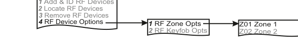
A three-column sub-menu flowchart. First column: 1 Add & ID RF Devices / 2 Locate RF Devices / 3 Remove RF Devices. Arrow leads to second column: 1 Add&Id:RF Zones / 2 Add&Id:RF Keyfob / 3 Add&Id:RF Echo. Arrow from 1 Add&Id:RF Zones leads to Scanning RF Devs in the third column.
1 Add&Id: RF Zones— add and identify RF zone devices (including RF-PA)2 Add&Id: RF Keyfob— add and identify RF Keyfobs3 Add&Id: RF Echo— add and identify the RF-Echo
The system displays Devs Found - 000 when it starts scanning and as it finds its first device the display will change to Devs Found - 001. When the system has found all its devices, press PLAY/QUIT.
- Select the zone number to be added & Id'ed.
- Next, press the tamper switch for about a second.
- As you press the devices' tamper switches in sequence, you will hear an audible indication as each device is identified into the system.
The RF-Echo can have a delayed reaction.
RF Device Options (Programmable Settings)

A three-column navigation flowchart. First column: 1 Service Menu / 2 Devices Menu / 3 Zone Menu. Arrow to second column: 1 RF Devices Menu / 2 Wired Devices Menu. Arrow to third column: 1 Add & ID RF Devices / 2 Locate RF Devices / 3 Remove RF Devices / 4 RF Device Options (highlighted).
A three-column sub-menu flowchart. First column: 1 Add & ID RF Devices / 2 Locate RF Devices / 3 Remove RF Devices / 4 RF Device Options. Arrow to second column: 1 RF Zone Opts / 2 RF Keyfob Opts. Arrow to third column: Z01 Zone 1 / Z02 Zone 2.
The RF-PA's programmable options can be accessed as follows:
Menu navigation: 1 Service Menu → 2 Devices Menu → 1 RF Devices Menu → 4 RF Device Options
Go to the Devices Menu. Then RF Devs Menu. Next select the RF Device Options.
Sub-menu path: 4 RF Device Options → 1 RF Zone Opts → Select the RF-PA number in question (Z01, Z02, etc.)
From there go to RF Zone Opts and then select the RF-PA number in question.
Mon Sup (Monitored Supervisory)
You can now select Mon Sup (Monitored Supervisory signal). This is defaulted to YES. When the device is "lost" for >120 minutes, a supervisory alarm is flagged by the panel. This can be turned off by selecting NO.
| Setting | Description |
|---|---|
| Mon Sup YES | Supervisory alarm enabled (default) |
| Mon Sup NO | Supervisory alarm disabled |
We recommend that this feature is left as YES.
Locate RF Devices

A three-column navigation flowchart. First column: 1 Service Menu / 2 Devices Menu / 3 Zone Menu. Arrow to second column: 1 RF Devices Menu / 2 Wired Devices Menu. Arrow to third column: 1 Add & ID RF Devices / 2 Locate RF Devices (highlighted) / 3 Remove RF Devices / 4 RF Device Options.
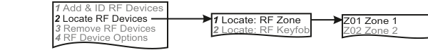
A three-column sub-menu flowchart. First column: 1 Add & ID RF Devices / 2 Locate RF Devices (highlighted) / 3 Remove RF Devices / 4 RF Device Options. Arrow to second column: 1 Locate: RF Zone / 2 Locate: RF Keyfob. Arrow to third column: Z01 Zone 1 / Z02 Zone 2.
The RF-PA can be located as follows:
Menu navigation: 1 Service Menu → 2 Devices Menu → 1 RF Devices Menu → 2 Locate RF Devices
Go to the Devices Menu. Then RF Devs Menu. Next select the Locate RF Devices.
Sub-menu path: 2 Locate RF Devices → 1 Locate: RF Zone → Select the RF-PA number in question
- From there go to Locate: RF Zone and then select the RF-PA number in question.
- The LED on the RF-PA that you selected will flash on and off every second thus helping you to locate it.
- Also note, opening & closing the tamper switch on a device will locate and display said device at the keypad.
Remove RF Devices

A three-column navigation flowchart. First column: 1 Service Menu / 2 Devices Menu / 3 Zone Menu. Arrow to second column: 1 RF Devices Menu / 2 Wired Devices Menu. Arrow to third column: 1 Add & ID RF Devices / 2 Locate RF Devices / 3 Remove RF Devices (highlighted) / 4 RF Device Options.
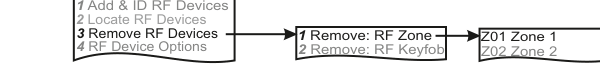
A three-column sub-menu flowchart. First column: 1 Add & ID RF Devices / 2 Locate RF Devices / 3 Remove RF Devices (highlighted) / 4 RF Device Options. Arrow to second column: 1 Remove: RF Zone / 2 Remove: RF Keyfob. Arrow to third column: Z01 Zone 1 / Z02 Zone 2.
The RF-PA can be removed as follows:
Menu navigation: 1 Service Menu → 2 Devices Menu → 1 RF Devices Menu → 3 Remove RF Devices
Go to the Devices Menu. Then RF Devs Menu. Next select the Remove RF Devices.
Sub-menu path: 3 Remove RF Devices → 1 Remove: RF Zone → Select the RF-PA number you want removed
- From there go to Remove: RF Zone and then select the RF-PA number you want removed. Press YES to select this device for removal and press YES again to confirm removal.
Specifications
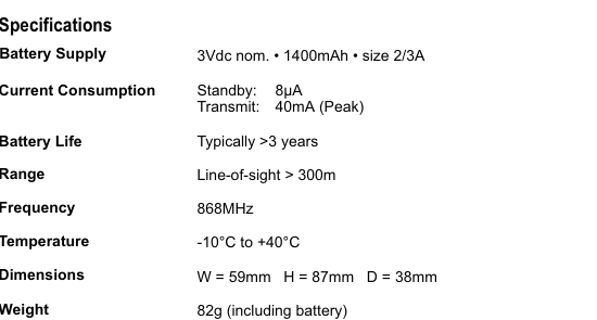
A two-column specifications table with parameter names in bold on the left and values on the right. Lists: Battery Supply — 3Vdc nom., 1400mAh, size 2/3A; Current Consumption — Standby: 8uA, Transmit: 40mA (Peak); Battery Life — Typically >3 years; Range — Line-of-sight > 300m; Frequency — 868MHz; Temperature — -10 degrees C to +40 degrees C; Dimensions — W=59mm H=87mm D=38mm; Weight — 82g (including battery).
| Parameter | Value |
|---|---|
| Battery Supply | 3Vdc nom. · 1400mAh · size 2/3A |
| Current Consumption | Standby: 8µA / Transmit: 40mA (Peak) |
| Battery Life | Typically >3 years |
| Range | Line-of-sight > 300m |
| Frequency | 868MHz |
| Temperature | -10°C to +40°C |
| Dimensions | W=59mm H=87mm D=38mm |
| Weight | 82g (including battery) |