RF-PIR (Wireless PIR Detector)
Hardware
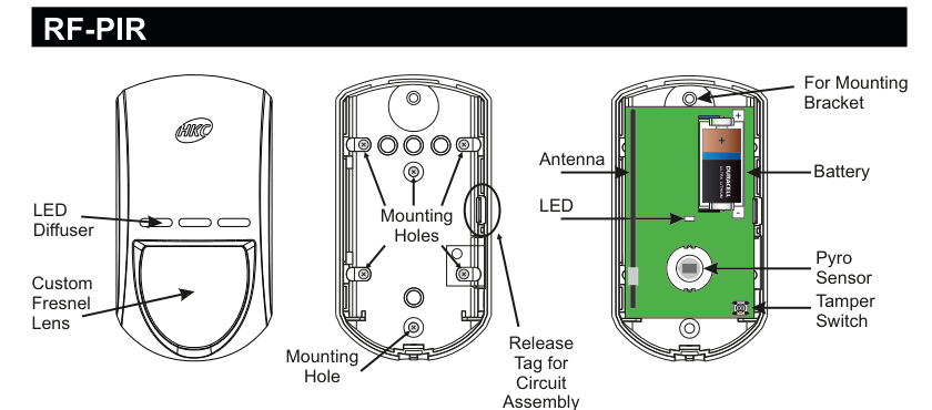
Front view (left): shows the LED diffuser window and custom Fresnel lens. Rear case (centre): shows mounting holes and mounting hole for bracket. Internal view (right): exploded view showing Tamper Switch (top), Mounting Bracket attachment point, Release Tag for Circuit Assembly, LED, Antenna, Pyro Sensor, and Battery compartment (Energizer Ultra Lithium 2/3A, 3V).
| Component | Description |
|---|---|
| LED Diffuser | Front window for status LED visibility |
| Custom Fresnel Lens | Front detection lens |
| Tamper Switch | Detects case opening (rear, top) |
| Mounting Holes | For wall/bracket mounting (rear) |
| Mounting Bracket | Optional mounting bracket attachment point |
| Release Tag | For circuit board assembly removal |
| LED | Status indicator |
| Antenna | RF communication antenna |
| Pyro Sensor | Passive infrared detection element |
| Battery | Energizer Ultra Lithium, 3Vdc, 2/3A size, 1400mAh |
Key Features
- 15m Detection range
- Recommend that battery is changed every 3 years
- >400m Line-of-sight Radio Range
- Close-in Detection
- Adjustable Sensitivity
- Noise Immunity
- Temperature Compensation
Add & ID on to the System
Procedure:
- Enter engineer mode on the SecureWave system.
- Open the RF-PIR and pull the isolator away from the battery — this powers it up.
- If you have multiple RF-PIRs, open them all at this stage and remove their isolators. Don’t close their lids yet.
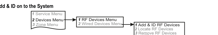
- Navigate to: Devices Menu → RF Devs Menu → Add & Id RF Devs.
- Add and identify the RF-PIR as a zone. The sub-menu offers three device types:

1 Add&Id: RF Zones— add zone devices (PIR, contact sensor, etc.)2 Add&Id: RF Keyfob— add keyfob devices3 Add&Id: RF Echo— add echo (repeater) devices
- The system displays
Devs Found - 000when scanning starts. As it finds devices, the count increments (e.g.Devs Found - 001). - When all devices are found, press PLAY/QUIT.
- Close the devices’ tamper switches by fitting their lids.
- As you close each tamper switch in sequence, you will hear an audible indication as each device is identified into the system.
The RF-Echo can have a delayed reaction.
RF Device Options (Programmable Settings)
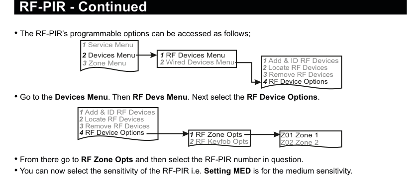
Menu path: 1 Service Menu → 2 Devices Menu → 1 RF Devices Menu → 4 RF Device Options
Then select:
1 RF Zone Opts→ select zone number (e.g.Z01 Zone 1)2 RF Keyfob Opts→ select keyfob number (e.g.Z02 Zone 2)
Sensitivity
You can set the sensitivity of the RF-PIR. There are three levels:
| Setting | Description |
|---|---|
| LOW | Low sensitivity |
| MED | Medium sensitivity (default) |
| HI | High sensitivity |
Monitored Supervisory (Mon Sup)
The Mon Sup (Monitored Supervisory) signal is defaulted to YES. When the device is “lost” for a prolonged period of time, a supervisory alarm is flagged by the panel. This can be turned off by selecting NO.
We recommend that this feature is left as YES.
Locate RF Devices
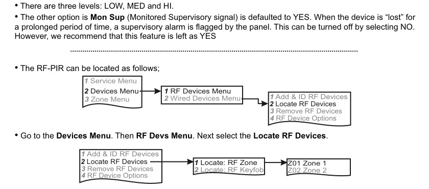
Menu path: 1 Service Menu → 2 Devices Menu → 1 RF Devices Menu → 2 Locate RF Devices
Then select:
1 Locate: RF Zone→ select zone number2 Locate: RF Keyfob→ select keyfob number
The LED on the selected RF-PIR will flash on and off every second, helping you to locate it.
Opening and closing the tamper switch on a device will also locate and display that device at the keypad.
Remove RF Devices
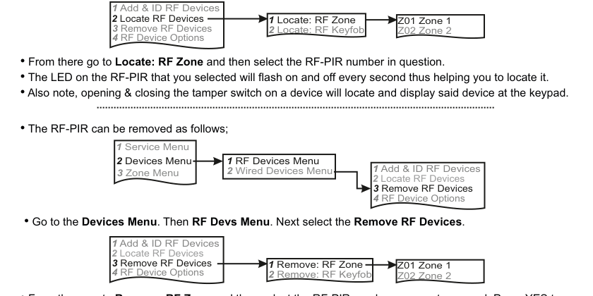
Menu path: 1 Service Menu → 2 Devices Menu → 1 RF Devices Menu → 3 Remove RF Devices
Then select:
1 Remove: RF Zone→ select zone number2 Remove: RF Keyfob→ select keyfob number
Press YES to select the device for removal, then press YES again to confirm removal.
Range of Detection
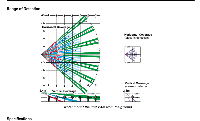
Four coverage diagrams: (1) Horizontal Coverage — fan-shaped top-down view with multiple detection beams (blue, red, green, magenta) extending to 14m at 2m intervals. (2) Horizontal Coverage (close-in detection) — smaller 2m × 4m close-range pattern. (3) Vertical Coverage — side view with beams from 2.4m mounting height angling to floor, reaching 14m. (4) Vertical Coverage (close-in detection) — side view within 1m–2m at 2.4m height.
Horizontal Coverage (top-down view):
- Main detection: fan-shaped pattern with multiple beams extending to 14m, with coverage zones at 2m, 4m, 6m, 8m, 10m, 12m, and 14m
- Close-in detection: concentrated coverage within 2m × 4m directly in front of the sensor
Vertical Coverage (side view, mounted at 2.4m):
- Main detection: beams angle downward from 2.4m mounting height to floor level, reaching out to 14m horizontally
- Close-in detection: short-range beams covering 1m–2m below the sensor
Mount the unit 2.4m from the ground.
Specifications
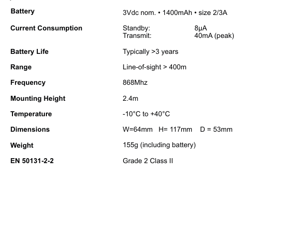
| Parameter | Value |
|---|---|
| Battery | 3Vdc nom. · 1400mAh · size 2/3A |
| Current Consumption | Standby: 8µA / Transmit: 40mA (peak) |
| Battery Life | Typically >3 years |
| Range | Line-of-sight > 400m |
| Frequency | 868MHz |
| Mounting Height | 2.4m |
| Temperature | -10°C to +40°C |
| Dimensions | W=64mm H=117mm D=53mm |
| Weight | 155g (including battery) |
| EN 50131-2-2 | Grade 2 Class II |