SW-10270 Panel / Output Card
You can convert some of your hardwired zones (zones 5, 6, 7 & 8) into Point ID buses. This allows you to wire-in a maximum of five Output Cards per ID bus (i.e. twenty in total).
- Wire-up zone (see wiring example below).
- In engineer mode, scroll to the Zone Menu. Press YES and scroll to Zone Hardware. Press YES again. Scroll down to the zone you are interested in (e.g. in the wiring examples below you would select zone 5 and 6).
- Scroll to Point ID. Then press YES. The system will automatically check the data bus for all Output Cards. When the scanning finishes, quit from this branch of the menu....
Zone Hardware Menu
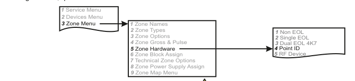
A three-column menu navigation flowchart. First column: 1 Service Menu / 2 Devices Menu / 3 Zone Menu (highlighted). Arrow leads to second column: 1 Zone Names / 2 Zone Types / 3 Zone Options / 4 Zone Gross & Pulse / 5 Zone Hardware (highlighted, bold) / 6 Zone Block Assign / 7 Technical Zone Options / 8 Zone Power Supply Assign / 9 Zone Map Menu. Arrow from 5 Zone Hardware leads to third column: 1 Non EOL / 2 Single EOL / 3 Dual EOL 4K7 / 4 Point ID (highlighted) / 5 RF Device.
Wiring Diagram
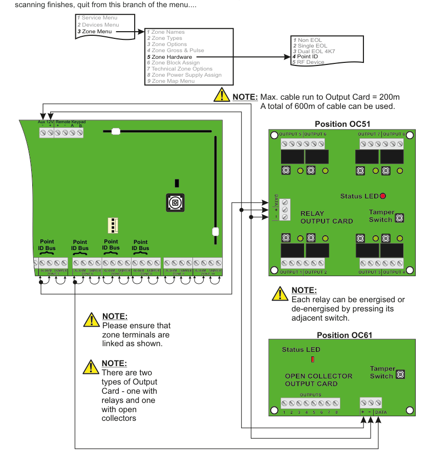
A wiring diagram showing the SW-10270 panel (green PCB, left) connected to two types of Output Card via Point ID buses on zones 5-8. The panel shows Aux 12V, Remote Keypad (+, -, A, B) connectors at the top, and four Point ID Bus connections on zones 5, 6, 7, and 8 at the bottom. Zone terminals are linked as shown with ALARM and TAMPER terminals on each zone.
Position OC51 (top-right): A Relay Output Card (green PCB) with four relay modules labelled OUTPUT 5, OUTPUT 6, OUTPUT 7, OUTPUT 8 across the top and OUTPUT 1, OUTPUT 2, OUTPUT 3, OUTPUT 4 across the bottom. Each relay has an adjacent push switch. The card has a Status LED (red), a Tamper Switch, and DATA, +, - connection terminals. Connected to the panel via the Point ID bus.
Position OC61 (bottom-right): An Open Collector Output Card (green PCB) with screw terminals labelled OUTPUTS 1-8, and +, -, DATA connection terminals. The card has a Status LED (red) and a Tamper Switch. Connected to the panel via the Point ID bus.
The zone-menu flowchart is shown at the top of the diagram: 3 Zone Menu -> 5 Zone Hardware -> 4 Point ID.
Max. cable run to Output Card = 200m. A total of 600m of cable can be used.
Please ensure that zone terminals are linked as shown.
There are two types of Output Card - one with relays and one with open collectors.
Each relay can be energised or de-energised by pressing its adjacent switch.
Example: Adding an Output Card in position 51
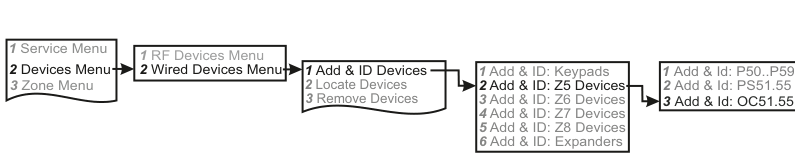
A five-column menu navigation flowchart. First column: 1 Service Menu / 2 Devices Menu (highlighted, bold) / 3 Zone Menu. Arrow to second column: 1 RF Devices Menu / 2 Wired Devices Menu (highlighted, bold). Arrow to third column: 1 Add & ID Devices (highlighted, bold) / 2 Locate Devices / 3 Remove Devices. Arrow to fourth column: 1 Add & ID: Keypads / 2 Add & ID: Z5 Devices (highlighted, bold) / 3 Add & ID: Z6 Devices / 4 Add & ID: Z7 Devices / 5 Add & ID: Z8 Devices / 6 Add & ID: Expanders. Arrow to fifth column: 1 Add & Id: P50..P59 / 2 Add & Id: PS51.55 / 3 Add & Id: OC51.55 (highlighted, bold).
- Go to Devices Menu and select YES. Scroll to Wired Devices Menu and press YES. Then select Add & Id Devices.
- Add & Id:Keypads will be on the display. Scroll to Add & Id:Z5 Devs. This is shorthand for: Add and identify devices on zone 5's data bus.
- Press YES.
- Add & Id:P50..59 will be on the display. Scroll to Add & Id:OC51.55. This is shorthand for: Add and identify any output cards on zone 5's data bus and name them Output Card 51, Output Card 52 etc.
- Press YES.
- When prompted, close the tamper switch on the Output Card. The 1st Output Card has now been added to the system in location OC51. The system is now ready to accept the 2nd Output Card in location OC52 and so on.
Example: Programming output number 1 on output card OC51

A four-column menu navigation flowchart. First column: 6 Timers Menu / 7 Outputs Menu (highlighted, bold) / 8 System Options. Arrow to second column: 1 Panel Outputs / 2 Expander Outputs / 3 PSU Outputs / 4 Output Card Outputs (highlighted, bold) / 5 Output Groups. Arrow to third column: OC51 Outputs (highlighted) / OC52 Outputs / OC53 Outputs. Arrow to fourth column: O1 Unused - / O2 Unused - / O3 Unused -.
- Go to Outputs Menu and select YES. Scroll to OPC Outputs and press YES. OPC is shorthand for Output Card.
- OC51 Outputs will be on the display. Press YES or scroll to other output card numbers and then press YES.
- You should see O1 Unused - on the display. Press YES or scroll to other individual output numbers on the card in question and then press YES. You can now select an output type from the list on page 75.
- Once you have selected your output type you will be prompted to select between negative or positive polarity.
Example: Locating Output Card in position 51
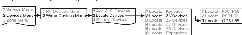
A five-column menu navigation flowchart. First column: 1 Service Menu / 2 Devices Menu (highlighted, bold) / 3 Zone Menu. Arrow to second column: 1 RF Devices Menu / 2 Wired Devices Menu (highlighted, bold). Arrow to third column: 1 Add & ID Devices / 2 Locate Devices (highlighted, bold) / 3 Remove Devices. Arrow to fourth column: 1 Locate : Keypads / 2 Locate : Z5 Devices (highlighted, bold) / 3 Locate : Z6 Devices / 4 Locate : Z7 Devices / 5 Locate : Z8 Devices / 6 Locate : Expanders. Arrow to fifth column: 1 Locate : P50..P59 / 2 Locate : PS51.55 / 3 Locate : OC51.55 (highlighted, bold).
- Go to Devices Menu and select YES. Scroll to Wired Devices Menu and press YES. Then select Locate Devices.
- Locate:Keypads will be on the display. Scroll to Locate:Z5 Devs. Press YES.
- Locate:P50..59 will be on the display. Scroll to Locate:OC51.55. Press YES.
- OC51 OutputCd 51 will be on the display and the status LED on Output Card 51 will be flashing on and off every second. Pressing NEXT brings to Output Card 52 and so on.
Open Collector Output Card with 3rd Party External Dialler
One use to be made of the Open Collector Output Card is to drive a 3rd party external dialler as illustrated.
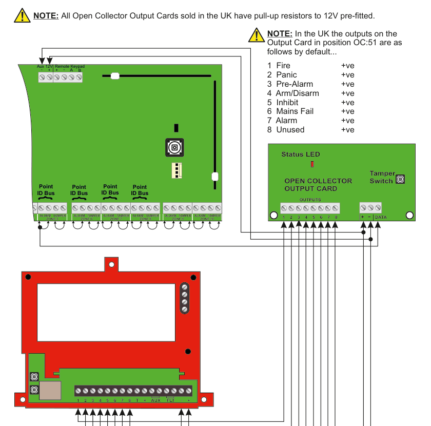
A wiring diagram showing the SW-10270 panel (green PCB, top-left) connected via a Point ID bus to an Open Collector Output Card (green PCB, top-right), which in turn is wired to a 3rd party external dialler (red PCB, bottom). The panel shows zones 5-8 with Point ID Bus connections and zone terminals (ALARM, TAMPER) on each zone. The Open Collector Output Card has OUTPUTS terminals 1-8, and +, -, DATA terminals. Wires run from the eight output terminals down to the external dialler's terminal strip (labelled 1, 2, 3, 4, 5, 6, 7, 8, T, +, AUX, FLT, -, +). The external dialler is a red PCB with a display screen, mounting holes, and a green terminal strip at the bottom.
The UK default output assignments for the Output Card in position OC:51 are shown to the right of the diagram.
All Open Collector Output Cards sold in the UK have pull-up resistors to 12V pre-fitted.
In the UK the outputs on the Output Card in position OC:51 are as follows by default...
| Output | Function | Polarity |
|---|---|---|
| 1 | Fire | +ve |
| 2 | Panic | +ve |
| 3 | Pre-Alarm | +ve |
| 4 | Arm/Disarm | +ve |
| 5 | Inhibit | +ve |
| 6 | Mains Fail | +ve |
| 7 | Alarm | +ve |
| 8 | Unused | +ve |