Outputs Menu
Output Hardware Types
There are three types of hardware associated with the Panel Outputs.
Fig. 1 -- Open Drain Output (Output 1 & 2)

Open Drain circuit (FET version of an Open Collector). Shows a MOSFET transistor with a 47 Ohm resistor, two 0V terminals, and the output terminal. Labelled "Output 1 & 2".
- Type: Open Drain (FET version of an Open Collector)
- Max. current: 100mA each
- Panel outputs: 1 and 2
- Also the type used on the ID 8 Open Collect Output Card
Fig. 2 -- Open Collector Output (Output 3, 4 & 5)
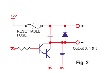
High current Open Collector circuit. Shows a bipolar transistor with a resettable fuse, 12V supply rail, positive (+) and negative (-) output terminals, and two 0V terminals. Labelled "Output 3, 4 & 5".
- Type: Open Collector (high current)
- Max. current: 300mA each
- Panel outputs: 3, 4 and 5
- Used to trigger sirens and strobes
- These outputs also have 12V supply terminals associated with them to power said devices
Fig. 3 -- Relay Output (Output 7 and upwards)
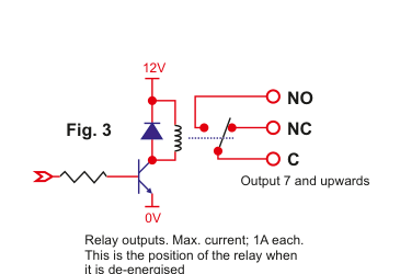
Relay output circuit. Shows a relay coil driven by a transistor, with 12V supply, 0V terminal, and three relay contact terminals: NO (Normally Open), NC (Normally Closed), and C (Common). The diagram shows the relay in its de-energised position. Labelled "Output 7 and upwards".
- Type: Relay
- Max. current: 1A each
- Panel outputs: 7 and upwards
- There are 2 relay outputs on each 10-Zone expander
- Relay outputs are quite versatile and robust -- good for CCTV servos etc.
- Also the type used on the ID 8 Relay Output Card and Power Supply Units
For legacy reasons, there is no output 6.
Output ON/OFF Wiring
In this configuration the output can either sink current when the transistor is on or not sink current when off. This is ideal if you want to wire-in a relay or buzzer.
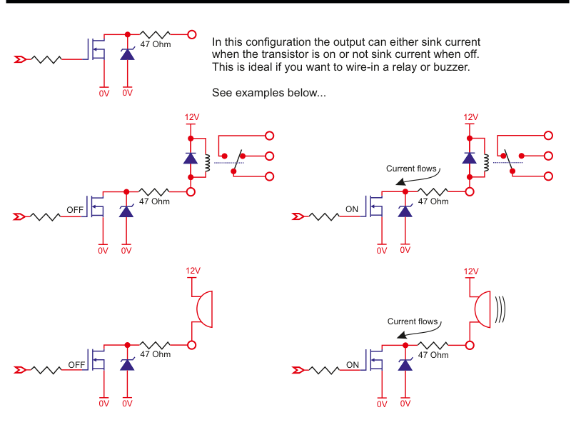
Six circuit diagrams arranged in two rows. Top row (relay wiring): Left shows an OFF state with an open-drain output driving a relay (de-energised), right shows the ON state with current flowing through the relay (energised). Bottom row (buzzer/siren wiring): Left shows an OFF state driving a siren/buzzer (not sounding), right shows the ON state with current flowing through the siren/buzzer (sounding). Each diagram includes the 12V supply, 47 Ohm resistor, transistor, and 0V terminals.
Pull-Up Resistor for High Impedance Loads
However, without a device like a relay or a buzzer wired into it, the voltage observed on such outputs cannot be determined. This is a problem if you are wiring into something with a high input impedance like an external dialler. In this case you will need a pull-up resistor.
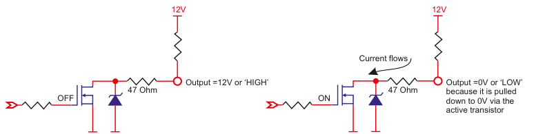
Two circuit diagrams showing the use of a pull-up resistor. Left (OFF state): The transistor is off, the pull-up resistor pulls the output to 12V, giving Output = 12V or 'HIGH'. Right (ON state): The transistor is on, current flows through the pull-up resistor to ground, giving Output = 0V or 'LOW' because it is pulled down to 0V via the active transistor.
In this example an OFF signal gives you a HIGH output while an ON gives you a LOW.
Outputs Menu Structure
The Outputs Menu contains the following sub-menus:
| Sub-menu | Description |
|---|---|
| 71 Panel Outputs | Select output type for outputs 1 to 5 |
| 72 Expander Outputs | Configure outputs on 10-Zone Expanders (2 per expander) |
| 73 PSU Outputs | Configure outputs on Power Supply Units (2 per PSU) |
| 74 O/P Card Outputs | Configure outputs on Output Cards (8 per OPC) |
| 75 Output Groups | Cluster outputs into groups (see Output Groups below) |
| 76 User Outputs | Configure user-controllable outputs (see User Outputs below) |
Panel Outputs is used to select the output type you want for outputs 1 to 5. See the Output Options table below for the full range of output types.
Please note that each 10-Zone Expander has 2 outputs (Expander Outputs), each power supply has 2 outputs (PSU Outputs) and each Output Card has 8 outputs (OPC Outputs).
Example: Programming the Outputs on the Panel
- Go to Outputs Menu and select YES.
- Panel Outputs will be on the display. Again, press YES.
- You should see 01 Pre Alrm + on the display. Press YES or scroll to another output and then press YES.
- In this example Pre Alrm (shorthand for Pre-Alarm) will flash on the display.
- You can now scroll and select an output type from the list below.
- Once you have selected your output type you will be prompted to select between negative or positive polarity.
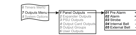
Menu navigation flowchart. From the main menu (6 Timers Menu, 7 Outputs Menu, 8 System Options) an arrow leads to the sub-menus (1 Panel Outputs, 2 Expander Outputs, 3 PSU Outputs, 4 Output Card Outputs, 5 Output Groups, 6 User Outputs). A second arrow leads to the default output assignments: 01 Pre Alarm (+ve), 02 Alarm (+ve), 03 Strobe (-ve), 04 Internal Bell (-ve), 05 External Bell (-ve).
Output Options
The following table lists all available output types. See descriptions below for each type.
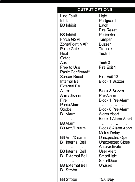
Two-column list titled "OUTPUT OPTIONS" showing all available output types. Left column (bottom to top): Internal Bell, External Bell, Alarm, Arm/Disarm, Fire, Panic Alarm, Strobe, B1 Alarm through B8 Alarm, B0 Arm/Disarm through B8 Arm/Disarm, B1 Internal Bell through B8 Internal Bell, B1 External Bell through B8 External Bell, B1 Strobe through B8 Strobe. Right column (top to bottom): Light, Partguard, Latch, Fire Reset, Perimeter, Tamper, Buzzer, Trouble, Tech 1 through Tech 8, Fire Exit 1 through Fire Exit 12, Block 1 Buzzer through Block 8 Buzzer, Pre-Alarm, Block 1 Pre-Alarm through Block 8 Pre-Alarm, Alarm Abort, Block 1 Alarm Abort through Block 8 Alarm Abort, Mains Delay, Unexpected Open, Unexpected Close, Auto-activate, User Alert, SmartLight, SmartDoor, Unused. Additional types in the left column: Line Fault, Inhibit, B0 Inhibit through B8 Inhibit, Force GSM, Zone/Point MAP, Pulse Gate, Heat, Gates, Aux, Free to Use, Panic Confirmed (UK only), Sensor Reset.
Output Type Descriptions
| Output Type | Description |
|---|---|
| Int. Bell | Internal bell output activates when there is an alarm condition. Also activates during engineer mode in some menus e.g. Walk Test. This output is timed and is controlled by the Internal Bell Timer. |
| Ext. Bell | External bell output activates when there is an alarm condition. This output is timed and is controlled by the External Bell Timer. |
| Alarm | Alarm output activates when there is a verified alarm e.g. after a second zone is triggered. This output deactivates at disarm or when the panel rearms after an alarm. This output is known as Confirm in the UK. |
| ArmDisarm | The ArmDisarm output is used to indicate the armed state of the panel. It is not affected when the system is in Part Set. This output is activated when the system is armed and deactivated when the system is unset. |
| Fire | The Fire output is activated when a Fire zone is triggered. A user code is required to deactivate it. |
| Panic | The Panic output is activated in the event of a panic zone opening, a duress code being keyed-in or *# being entered simultaneously at the keypad (if enabled). A user code is required to deactivate it. |
| Strobe | Strobe output activates when there is a pre-alarm/alarm condition. Unlike the Internal bell output, this output is not timed but is only deactivated by a user code. |
| Light | The light output is controlled by the LIGHT key on the RKP. The state of the output is toggled when this key is pressed. |
| PartSet | The PartSet output is activated after the panel has been partially set or armed. It is deactivated when the system is unset. |
| Latch | The Latch output type is normally at 0V. At the start of Exit Time it switches from 0V to HIGH and stays HIGH until the system is unset. |
| FireReset | The FireReset output is normally at 0V. In the event of a fire alarm, the FireReset output will go HIGH for 2 seconds the next time the panel is armed. The FireReset output also switches HIGH for 2 seconds after exiting Engineer Mode and 15 seconds after an alarm activation in the Walk Test Menu. |
| Perimeter | The Perimeter output is deactivated when the panel is unset. Assuming the system is armed and a zone has the Perimeter option, the output will activate when that zone has either a pulse or gross alarm. The output will deactivate when the panel rearms. |
| Tamper | Tamper output activates when there is a tamper activation. This output deactivates with a valid user code. |
| Buzzer | The buzzer output follows the state of the buzzer on the keypads i.e. active when the buzzer is on and not active when the buzzer is off. |
| Trouble | The Trouble output activates when there is a fault or tamper on the system e.g. mains fail, line fault, low battery etc. It deactivates when the fault or tamper clears. |
| Tech 1 ... 8 | The Technical outputs (1-8) follow the state of their respective Technical inputs i.e. normally deactivated when their associated zone is closed and active when the zone is open. |
| Fire Exit 1 ... 12 | The Fire Exit outputs (1-12) follow the state of their respective Fire Exit inputs (like Technical inputs) but with added features like a delay time, user code intervention, internal bell option etc. They are normally deactivated when their associated zone is closed and active when the zone is open. |
| Pre-Alarm | Pre-alarm output triggers when the 1st alarm zone activates. It deactivates at disarm or at the end of the Alarm Abort Time. This is known as Intruder in the UK. |
| Alarm Abort | Alarm Abort output activates if there has been a pre-alarm followed by a disarm during the Alarm Abort Time. It deactivates at disarm or at the end of the Alarm Abort Time. |
| Mains Delay | The Mains Delay output will activate when there is a mains failure which exceeds the Mains Fault Delay Time (programmed in Misc. Timers). It will deactivate when the mains electricity is restored. |
| Unexpected Open | The Unexpected Open event timer is used as a flag if a premises is opened outside of programmed time limits. An Unexpected Open output will activate if the panel is in an unset state at end of closing time (i.e. Close Finish time). The output remains in this state until it is armed, or the start of opening time (i.e. Open Start time) is reached. |
| Unexpected Close | The Unexpected Close event timer is used as a flag if a premises is closed outside of programmed time limits. An Unexpected Close output will activate if the panel is in an armed state at end of opening time (i.e. Open Finish time). The output remains in this state until it is unset, or the start of closing time (i.e. Close Start time) is reached. |
| Auto-Activate | The Auto Activate event timer is used outside of normal business hours to trigger an alarm should the premises remain open longer than the programmed Interval Time. When the panel is unset by a non-24hour user (e.g. a cleaner) it must be re-armed within the Interval Time or the output will activate and the panel will go into alarm. |
| User Alert | The User Alert timer is used as a checking mechanism to ensure a user is still on the premises (e.g. a night watchman). Between the Start Time and End Time the user must check-in with the panel within a specified Interval Time. Each time they check-in the timer is reset to the interval time. If the timer runs for the full interval without a check-in then the User Alert output type will activate. This feature only works on the Days programmed to YES. In order to remind the user to check-in, the keypad will start beeping when the timer has 2 mins to run. Users will check-in by keying-in 0*5 followed by their user code. |
| SmartLight | A SmartLight output can be set to be triggered by just a zone opening or by just a user code or it can be set to be triggered by both. An Interval time needs to be programmed and is the amount of time the light will remain on for when triggered. If a user code is only to be used to operate a SmartLight, the option for that user should have "Output Only" set to YES. Note: the time is in minutes. |
| SmartDoor | A SmartDoor output can be set to be triggered by just a zone opening or by just a user code or it can be set to be triggered by both. An Interval time needs to be programmed and is the amount of time the door will open for when triggered. If a user code is only to be used to operate a SmartDoor, the option for that user should have "Output Only" set to YES. Note: the time is in seconds. |
| Unused | The Unused output has no function and is used to disable an output. |
| Line Fault | If you have a dialler and the telephone line voltage drops off, the Line Fault output will, after a short delay, activate. It will also activate if you have a GSM communicator enabled and the GSM network goes down. |
| Inhibit | The Inhibit output activates whenever a zone or point is inhibited. |
| Force GSM | The Force GSM output is used in conjunction with standalone GSM units configured as a dual path (PSTN & GSM) routers to monitoring stations. Typically wired into the "Force GSM" input of the router, it toggles between being active and not being active so that both paths are exercised when the system is doing its regular test call sequence. |
| Zone/Point MAP | This is a special output type that activates in conjunction with mapped zone or point inputs. See Output Groups and Mapped Output Options below. |
| Pulse Gate | If a user sends their user code followed by a space and then the word GATE via an SMS message to their system, a User Output configured as "Pulse Gate" will activate for 5 seconds. This time is programmable. |
| Heat | If a user sends their user code followed by a space and then the phrase HEAT ON via an SMS message to their system, a User Output configured as "Heat" will activate. HEAT OFF will deactivate the output. |
| Gates | If a user sends their user code followed by a space and then the phrase GATES ON via an SMS message to their system, a User Output configured as "Gates" will activate. GATES OFF will deactivate the output. |
| Aux | If a user sends their user code followed by a space and then the phrase AUX ON via an SMS message to their system, a User Output configured as "Aux" will activate. AUX OFF will deactivate the output. |
| Free to use | "Free to use" is another User Output and it is configurable. In this example change the phrase "Free to use" to something more meaningful e.g. PUMP. Now if a user sends their user code followed by a space and then the phrase PUMP ON via an SMS message to their system, the User Output will activate. PUMP OFF will deactivate the output. Note also that PUMP 10S will activate the output for 10 seconds, PUMP 10M for 10 minutes, PUMP 10H for 10 hours and PUMP 10D for 10 days. |
| Panic Confirmed | In the UK, to comply with BS 8243, you may not get a police response unless you activate two or more hold-up (or panic alarm) devices. When that does happen, the Panic Conf output will activate. (UK only) |
| Sensor Reset | If you have an alarm activation and then unset and rearm the system the SensorReset output will momentarily activate. Used to clear-down latching detectors. |
A typical set-up for a shop using Unexpected Open/Close timers might be: Open Start = 7:00, Open Finish = 9:00, Close Start = 17:30 & Close Finish = 18:30 (Monday - Saturday).
Heat, Gates and Aux can also be renamed in the same way as Free to use above.
Block-Specific Output Types
In addition to the main output types listed above, block-specific variants are available:
| Block Output Type | Range |
|---|---|
| B1 Alarm ... B8 Alarm | Alarm output for specific blocks 1-8 |
| B0 Arm/Disarm ... B8 Arm/Disarm | Arm/Disarm output for specific blocks 0-8 |
| B1 Internal Bell ... B8 Internal Bell | Internal Bell output for specific blocks 1-8 |
| B1 External Bell ... B8 External Bell | External Bell output for specific blocks 1-8 |
| B1 Strobe ... B8 Strobe | Strobe output for specific blocks 1-8 |
| Block 1 Buzzer ... Block 8 Buzzer | Buzzer output for specific blocks 1-8 |
| Block 1 Pre-Alarm ... Block 8 Pre-Alarm | Pre-Alarm output for specific blocks 1-8 |
| Block 1 Alarm Abort ... Block 8 Alarm Abort | Alarm Abort output for specific blocks 1-8 |
| B0 Inhibit ... B8 Inhibit | Inhibit output for specific blocks 0-8 |
Output Groups (75)
The system can be set up in such a way as to cluster outputs into groups. There can be up to 32 groups and each group can have up to 4 outputs. An output can be in two or more groups at the same time.
Once you start assigning outputs to groups the output type changes to Zone/Pt MAP. So if your output was an Alarm output for instance and you assign it to a group, it no longer is an Alarm output; it becomes a zone (or point) mapped output.
Once you have set up your output groups you can then go to Zone Map Menu in the Zone Menu and assign zones to those groups. The objective is to trigger a group of outputs when a zone or group of zones activate.
Assigning Outputs to Groups
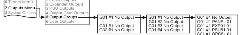
Menu navigation flowchart. From the main menu (6 Timers Menu, 7 Outputs Menu, 8 System Options) the path leads to the sub-menus (1 Panel Outputs through 6 User Outputs) with an arrow to 5 Output Groups. This branches to group selection (G01 #1 No Output ... G31 #1 No Output, G32 #1 No Output), then to output slot selection within the group (G01 #1 through G01 #4 No Output), then to output assignment from the four sections (G01 #1 PANEL 01, G01 #1 EXP01 01, G01 #1 PSU51 01, G01 #1 OPC51 01).
Procedure:
- Go to Outputs Menu and press YES. Scroll to Output Groups and press YES.
- You will see G01 #1 No Output on the display. The group number will be flashing. If you want to set up Group 01 press YES now or scroll to your preferred group number and then press YES.
- You will now see the digit 1 flashing. Press YES.
- This is where you assign the 1st output of the group. No Output will be flashing. Pressing the NEXT button will bring you to the four different output sections i.e. those on-board the main panel itself (PANEL), those on 10-Zone expanders (EXP), those on power supplies (PSU) and finally those on output cards (OPC). Once you have settled on one of those four sections press YES. Now you will notice the specific output number flashing. Press YES or scroll to your preferred number and then select by pressing YES.
- Once you have assigned the 1st output of the group you will be back to digit 1 flashing. This is a prompt to move on to assigning the 2nd output of the group. Press NEXT followed by YES and follow the steps as above etc.
Assigning Zones to Output Groups (Zone Map Menu)
It is then time to go to Zone Map Menu in the Zone Menu to assign zones to your output groups.
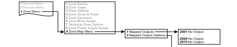
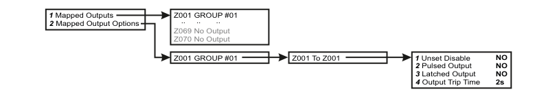
Menu navigation flowchart. From the service menu path (1 Service Menu, 2 Devices Menu, 3 Zone Menu) an arrow leads to the Zone Menu sub-items (1 Zone Names through 8 Zone Power Supply Assign, 9 Zone Map Menu). From Zone Map Menu, two sub-menus branch: 1 Mapped Outputs and 2 Mapped Output Options. Mapped Outputs shows zone assignments (Z001 No Output ... Z069 No Output, Z070 No Output).
Procedure:
- Go to Zone Menu and press YES. Scroll to Zone Map Menu and press YES.
- You will see Mapped Outputs on the display. Press YES.
- You will see Z001 No Output on the display. Pressing NEXT would scroll on to zone 2 but if instead you press YES, the No Output will start to flash; this is your prompt to assign zone 1 to an output group.
- Press NEXT until you scroll to Z001 GROUP #01. Press YES. The group number will now start to flash.
- Press YES or scroll to your preferred group number and then assign by pressing YES.
- In this example, if you press YES without scrolling, you would have assigned zone 1 to output group 1. If zone 1 activates then those outputs assigned to output group 1 will trigger.
Mapped Output Options
Menu navigation flowchart. From the Zone Map Menu sub-items (1 Mapped Outputs, 2 Mapped Output Options), the top branch shows Mapped Outputs leading to zone-group assignments (Z001 GROUP #01 ... Z069 No Output, Z070 No Output). The bottom branch shows Mapped Output Options leading to Z001 GROUP #01 then Z001 To Z001, then to the four configurable options: 1 Unset Disable (NO), 2 Pulsed Output (NO), 3 Latched Output (NO), 4 Output Trip Time (2s).
Procedure:
- Go to Zone Menu and press YES. Scroll to Zone Map Menu and press YES.
- You will see Mapped Outputs on the display. Scroll to Mapped O/P Opts and press YES.
- Following on from the example above you will see Z001 GROUP #01 on the display. Pressing YES brings Z001 To Z001 to the display. For this example, press YES.
- First up is Unset Disable NO. If you change to YES the outputs in group 1 will not trigger when the system is in the unset state.
- Next option is Pulsed O/P NO. If you change this to YES the outputs in group 1 will activate for a few seconds (see O/P Trip Time below).
- Next option is Latched O/P NO. If you change this to YES the outputs in group 1 will activate and stay activated until the system is unset (or if already in an unset state, the system is armed and then unset).
- Finally, O/P Trip Time is where you can adjust the pulse time. Normally this is 2 seconds but can be programmed to be up to 99 seconds.
| Option | Default | Description |
|---|---|---|
| Unset Disable | NO | If YES, outputs in the group will not trigger when the system is in the unset state |
| Pulsed Output | NO | If YES, outputs in the group will activate for a few seconds (see Output Trip Time) |
| Latched Output | NO | If YES, outputs in the group will activate and stay activated until the system is unset (or if already unset, until armed and then unset) |
| Output Trip Time | 2s | Adjustable pulse time from 2 to 99 seconds |
If you leave both Pulsed O/P and Latched O/P options set to NO then the outputs simply follow the status of its zone. In this example, if zone 1 is open the outputs in group 1 trigger and when it is closed they are not triggered.
User Outputs (76)
User Outputs are special outputs that can be controlled by the user if they send certain commands to the system via an SMS text message (or, alternatively by using the 0*8 Quick Key command).
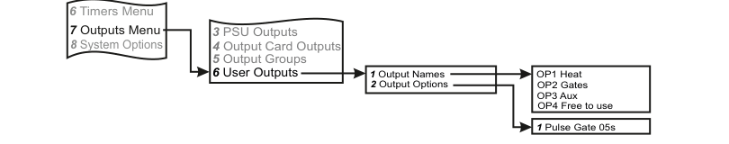
Menu navigation flowchart. From the main menu (6 Timers Menu, 7 Outputs Menu, 8 System Options) the path leads to the sub-menus with an arrow to 6 User Outputs. This branches to two sub-menus: 1 Output Names (showing OP1 Heat, OP2 Gates, OP3 Aux, OP4 Free to use) and 2 Output Options (showing 1 Pulse Gate 05s).
Example: Programming a User Output on one of the Panel Outputs
- Go to Outputs Menu and select YES.
- Panel Outputs will be on the display. Again, press YES.
- You should see 01 Pre Alrm + on the display. Press YES or scroll to another output and then press YES.
- In this example Pre Alrm (shorthand for Pre-Alarm) will flash on the display.
- You can now scroll & select a User Output type from this list: Pulse Gate, Heat, Gates, Aux & Free to use.
- For the example below, select Free to use.
- Once you have selected your output type you will be prompted to select between negative or positive.
- You can use any of the 4 User Outputs. So for instance, follow the menu below & scroll to OP4 Free to use. The 4 will be flashing. Press YES. You can now type in a new command e.g. PUMP. Again, press YES.
- OP4 PUMP will be on the display. The user can now send their user code followed by a space and then the phrase PUMP ON to trigger output 1 on the panel.
User Output Names
| Output | Default Name |
|---|---|
| OP1 | Heat |
| OP2 | Gates |
| OP3 | Aux |
| OP4 | Free to use |
User Output Options
There is one User Output Option: Pulse Gate 05s. Adjust this value to suit your particular gate controller.