Devices Menu
Default Eng. Code: 4567 | Default User Code: 1111 (Irl) / 1234 (UK)
21 - RF Devices Menu
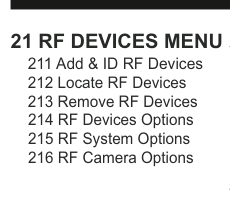
Menu tree for 21 RF Devices Menu with six sub-menus: 211 Add & ID RF Devices, 212 Locate RF Devices, 213 Remove RF Devices, 214 RF Devices Options, 215 RF System Options, 216 RF Camera Options.
| Sub-Menu | Description |
|---|---|
| 211 Add & ID RF Devices | Add RF devices to the wireless system |
| 212 Locate RF Devices | Locate a device that has been assigned an ID |
| 213 Remove RF Devices | Remove RF devices from the system |
| 214 RF Devices Options | Configure the behavior of individual wireless devices |
| 215 RF System Options | System-level RF settings (supervisory, jam detect) |
| 216 RF Camera Options | Configure RF camera image settings |
211 Add & ID RF Devices
Add & ID RF Devices is used to add devices (like RF detectors, RF sounders, RF keypads etc.) to the wireless system.
212 Locate RF Devices
Locate RF Devices, this menu is used to locate a device that has been assigned an ID. A device can be located by selecting it in this menu and noting its LED pattern.
213 Remove RF Devices
Remove RF Devices, this menu is used to remove a device from the system. Only a device that has been ID'ed can be removed from the system.
214 RF Devices Options
RF Devices Options is where you can configure the behavior of individual wireless devices.
These 4 sub-menus are dealt in detail for specific devices in pages 12-43.
215 RF System Options
There are 5 sections in the RF System Options sub-menu.
The Supervisory feature monitors the conditions of the radio paths between the panel and end devices.
With Sup. Reports (Supervisory Reports) set to YES you get a fault message if one of those radio paths is broken.
By default, a radio path needs to be broken for 120 minutes before you get a Supervisory Report. To change this time, go to Sup. Time (Supervisory Time) and select any time between 20 and 999 minutes.
You can also activate your internal bell (or siren) if you set Sup. Bells (Supervisory Bells) to YES. Only applies when system is armed. By default this feature is set to NO.
By its nature, an RF-Echo will have a small delay when activating so you might like to silence it during a Walk Test by setting WalkTst Bells (Walk Test Bells) to NO. By default it is set to YES.
RF Jam Detect is a feature that can flag a fault message whenever the radio channel is being jammed.
| Setting | Default | Description |
|---|---|---|
| Sup. Reports | YES | Fault message if a radio path is broken |
| Sup. Time | 120 min | Time (20–999 min) before a supervisory report is raised |
| Sup. Bells | NO | Activate internal bell on supervisory fault (armed only) |
| WalkTst Bells | YES | Sound RF-Echo bell during Walk Test |
| RF Jam Detect | YES | Flag a fault message when radio channel is jammed |
Contact Tech. Support if adjusting supervisory signal or jam detect. We advise that these settings be left as per the default settings (i.e. as YES).
216 RF Camera Options
There are 4 sections in the RF Camera Options sub-menu.
Image Size is defaulted to VGA which is 640x480 pixels. If you press YES you can toggle to QVGA which has a lower resolution of 320x240 pixels but has a quicker transmission time.
Color is defaulted to YES. You can select black and white by pressing NO but unless there are specific site-related reasons for choosing black and white we recommend keeping the colour on.
Num Images (Number of images) is defaulted to 3. When the system is armed and the PIRCAM is triggered, 3 snapshots are taken in 1 second intervals. This number can be changed by pressing YES and then pressing any number between 1 to 5.
Live images is defaulted to NO. When YES is selected, you can take a snapshot on your smart phone whenever you want. When you take a snapshot, the RF-PIRCAM's flash will always trigger even if the flash option is set to NO.
Live images requires panel s/w V3.3.4 or higher.
| Setting | Default | Description |
|---|---|---|
| Image Size | VGA (640x480) | Toggle to QVGA (320x240) for quicker transmission |
| Color | YES | Set to NO for black and white |
| Num Images | 3 | Number of snapshots when triggered (1–5) |
| Live images | NO | Take a snapshot on demand from your smart phone |
22 - Wired Devices Menu
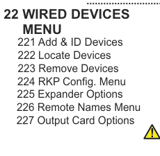
Menu tree for 22 Wired Devices Menu with seven sub-menus: 221 Add & ID Devices, 222 Locate Devices, 223 Remove Devices, 224 RKP Config. Menu, 225 Expander Options, 226 Remote Names Menu, 227 Output Card Options. A small caution triangle icon appears at the bottom right.
| Sub-Menu | Description |
|---|---|
| 221 Add & ID Devices | Add wired keypads, point ID sensors, expanders, PSUs, output cards |
| 222 Locate Devices | Locate identified wired devices |
| 223 Remove Devices | Remove wired devices from the system |
| 224 RKP Config. Menu | Keypad configuration |
| 225 Expander Options | Expander settings |
| 226 Remote Names Menu | Configure remote device names |
| 227 Output Card Options | Output card settings |
221 Add & ID Devices
Add & ID Devices is used to add:
- Wired Keypads (Add & Id:Keypads)
- Point ID devices to zone 5's bus (Add & Id:Z5 Devs)
- Point ID devices to zone 6's bus (Add & Id:Z6 Devs)
- Point ID devices to zone 7's bus (Add & Id:Z7 Devs)
- Point ID devices to zone 8's bus (Add & Id:Z8 Devs)
- Zone Expanders (Add & Id:Expandr)
- RF Expanders (Add & Id:RF Expand)
Point ID devices include inertia sensors, magnetic contacts, PIRs, power supplies and output cards.
222 Locate Devices
Locate Devices, this menu is used to locate a device that has been assigned an ID. A device can be located by selecting it in this menu and noting its LED pattern (which should turn on and off every second).
223 Remove Devices
Remove Devices, this menu is used to remove a device from the system. Only a device that has been ID'ed can be removed from the system. Scroll to device to remove then press YES to remove it. Pressing the tamper switch of a device will locate it but this is not strictly necessary.
224 RKP Configuration Menu
RKP Configuration Menu has 7 sections. The first, RKP Options Menu is used to select options for keypads. Options include whether the buzzer is enabled, whether audio messages are played and also whether the status LED's are enabled. The second, RKP Block Assign, is used to associate specific keypads with a block of zones.
A "block" is a semi-autonomous section within the overall system and is made up of zones/points, users, keypads and outputs.
The next 5 are, by and large, self-explanatory: Rkp LCD Contrast, Rkp Buzzer Volume, Rkp Audio Volume, Rkp Brightness & Rkp Key Volume. Except to say that Rkp Key Volume refers to the sound level of blips you hear when you press a button on the keypad.
| Setting | Description |
|---|---|
| RKP Options Menu | Buzzer, audio messages, status LED's |
| RKP Block Assign | Associate keypads with a block of zones |
| Rkp LCD Contrast | LCD contrast adjustment |
| Rkp Buzzer Volume | Buzzer volume adjustment |
| Rkp Audio Volume | Audio message volume adjustment |
| Rkp Brightness | Display brightness adjustment |
| Rkp Key Volume | Key-press blip sound level |
225 Expander Options
Expander Options Menu: used to disable the tamper switch.
226 Remote Names Menu
Remote Names Menu: used to type-in meaningful names associated with the devices. "Under Stairs", "In Garage" etc.
227 Output Card Options
Output Card Options: used to disable the tamper switch.