User Menu
Default Eng. Code: 4567 | Default User Code: 1111 (Irl) / 1234 (UK)
51 User Codes
This menu is used to program user codes for users 1 to 64. Each code is required to be 4-6 digits in length. The digit 0 is not allowed and codes cannot end with the number 9 as this would conflict with the duress facility (as would user codes that only differed by one digit). New codes must be verified in order to be accepted.
52 User Names
User names enable more detailed information to be displayed in the system log and are also used in the user menus.
53 User Options
Each user can be assigned a number of options. These are explained in detail below.
User Option Descriptions
| Option | Description |
|---|---|
| Full Set | Full set enables the user to fully arm the system using their code. |
| Unset | Allows a user to unset the system using their code. |
| Inhibit | Allows a user to inhibit zones or tampers using their code. |
| PartSet A | Allows a user to part set A the system within a user menu (See User Menu below). |
| PartSet B | Allows a user to part set B the system within a user menu (See User Menu below). |
| User Menu | The User Menu is used to generate a menu for the user. When they enter their code it will pop the user into a menu structure which contains the following items. |
| Manager Menu | Used to enter the manager menu (See Below). |
| Output Only | User codes assigned to Smart Door and/or Smart Light features can have Output Only option set to YES (and all the other options to NO), so that they can control the feature in question without accidentally arming the system. |
| 24 Hour | As a general rule, most User codes need to operate 24 hours a day except User codes associated with the Timed Access feature (in which case you set it to NO). See page 64. |
| Code&Prox | If set to YES then you need to key-in the User code and use prox tag to UNSET the system. |
User Menu Items
The User Menu provides a more secure way of accessing system functions. By disabling quick codes and giving the user the User Menu option only authorised users will be able to access the functions outlined below. The items in the menu are selected using the PREV and NEXT keys. Press the YES key to enter a menu item.
| Menu Item | Description |
|---|---|
| Full Arm | Used to fully arm the panel |
| Quick Arm | Used to fully arm the panel without an exit time |
| Part Set A | Used to part-set area A of the panel |
| Part Set B | Used to part-set area B of the panel |
| View User Log | Used to enter the View User Log menu |
| Walk Test | Used to enter User Walk Test |
| Chime On/Off | Used to toggle the chime operation |
| Bell Test | Used to do a bell test |
| Manager Menu | Used to enter the manager menu (See Below) |
Manager Menu Items
The manager menu is used to enable a user to change the following panel options.
| Menu Item | Description |
|---|---|
| Set Date & Time | Used to set the system date and time |
| View Eng. Log | Used to enter engineer view log |
| User Codes | Used to change a user code |
| User Options | Used to change user options |
| User Names | Used to change the name of a user |
| User Blk Assign | Used to assign User Codes to specific blocks |
| User ProxAssign | Used to assign User Codes to specific proximity tags |
| System Config? | Set Eng. Access to YES allows Engineer Code to work without needing the User Code as well. The internal sirens will activate when the system goes into Engineer Mode and can be silenced by pressing any key on the active keypad. |
Once the Manager Menu option has been selected the user will automatically have a User Menu as this is the only way that the Manager Menu can be accessed.
54 Engineer Code
This menu is used to program the engineer code for the system. The code is required to be 4-6 digits in length and must not contain 0. Unlike User codes, the engineer code can end with the digit 9.
55 User Block Assign
This is used to associate specific user codes to specific blocks. A block is a semi-autonomous alarm system within the overall system.
56 User Prox Assign
Used to associate specific users to specific proximity tags. Press YES. Then U01 Tag Unused will be on the display. Next, introduce the prox tag to the keypad. See page 38 for details.
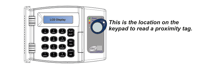
Keypad layout diagram showing the LCD Display at the top, number keys (1-9, 0, *, #) with letter labels, function keys (PLAY/QUIT, REC/YES, LIGHT/NO), and PREV/NEXT navigation keys. To the right of the keypad is the proximity tag reader (circular area with Power, Fault, and Alarm indicator LEDs) with annotation: "This is the location on the keypad to read a proximity tag." The keypad complies with EN 50131 Grade 2 Class II.
This is an option and is not available on all models.
57 Manufacturer's Code
This menu is used to reprogram the manufacturer's code for the system. The code is required to be 4-6 digits in length and must not contain 0. It too can end with the digit 9. The manufacturer's code is required when upgrading the panel's firmware (or software).