Point ID Sensors
Alternatively, you can convert your hardwired zone input into a Point ID bus. This allows you to wire-in a maximum of ten Point ID sensors per zone.
Wiring and Setup
- Wire-up zone (see wiring example below).
- Leave the covers of the sensors off for now.
- In engineer mode scroll to the Zone Menu. Press YES and scroll to Zone Hardware. Press YES again. Scroll down to Point ID. Then press YES. The system will automatically check the data bus for all Point ID sensors. When the scanning finishes, quit from this branch of the menu.
Zone Hardware Menu Navigation
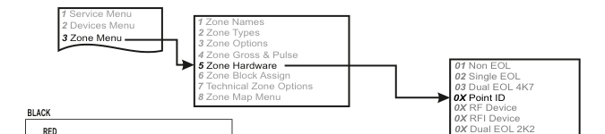
A three-column menu navigation flowchart. First column: 1 Service Menu / 2 Devices Menu / 3 Zone Menu. Arrow leads to second column: 1 Zone Names / 2 Zone Types / 3 Zone Options / 4 Zone Gross & Pulse / 5 Zone Hardware / 6 Zone Block Assign / 7 Technical Zone Options / 8 Zone Map Menu. Arrow from 5 Zone Hardware leads to third column: 01 Non EOL / 02 Single EOL / 03 Dual EOL 4K7 / 0X Point ID / 0X RF Device / 0X RFI Device / 0X Dual EOL 2K2.
Menu path: 3 Zone Menu → 5 Zone Hardware → 0X Point ID
Wiring Diagram
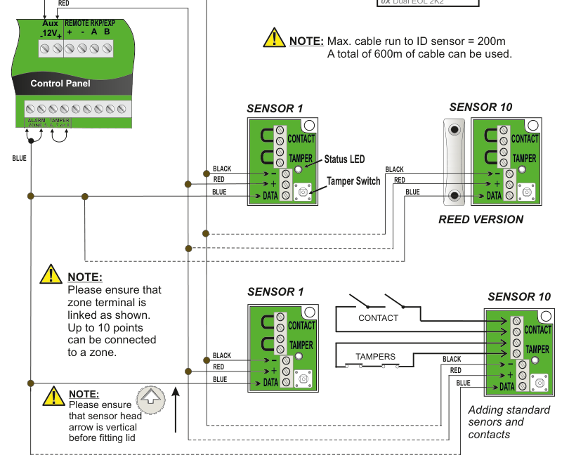
A wiring diagram showing how to connect Point ID sensors to the control panel. Control Panel (left) shows the Aux 12V and REMOTE RKP/EXP terminals (+, -, A, B) at the top, and zone terminals (ALARM, TAMPER, ZONE 5, 6, 7 or 8) at the bottom. Upper section (Reed Version): A RED wire runs from the zone terminal to the + terminal on SENSOR 1, a BLACK wire runs to the TAMPER terminal, and a BLUE wire runs to the DATA terminal. SENSOR 1 shows a Status LED and Tamper Switch. Wires continue in daisy-chain to SENSOR 10 with the same connections: BLACK to TAMPER, RED to +, BLUE to DATA. Labelled REED VERSION. Lower section (Adding standard sensors and contacts): SENSOR 1 and SENSOR 10 are wired with the same colour scheme (BLACK, RED, BLUE), with additional CONTACT and TAMPERS connections looped between sensors. Each sensor has CONTACT, TAMPER, +, -, and DATA terminals.
Wiring Connections
| Wire Colour | Terminal |
|---|---|
| BLACK | TAMPER |
| RED | + |
| BLUE | DATA |
Cable Length Limits
- Max. cable run to ID sensor = 200m
- A total of 600m of cable can be used.
Important Notes
Please ensure that zone terminal is linked as shown. Up to 10 points can be connected to a zone.
Please ensure that sensor head arrow is vertical before fitting lid.
Add & ID Devices
- Go to Devices Menu and select YES. Scroll to Wired Devices Menu and press YES. Then select Add & Id Devices.
- When prompted, close the tamper switch on the sensor. The 1st Point ID sensor has now been added to the system in location P01. The system is now ready to accept the 2nd Point ID sensor in location P02 and so on.
If you have already mapped a wireless detector on to Zone in question, it cannot be used as a Point ID bus unless you remove that wireless device and map it on to another zone number instead.
Add & ID Menu Navigation
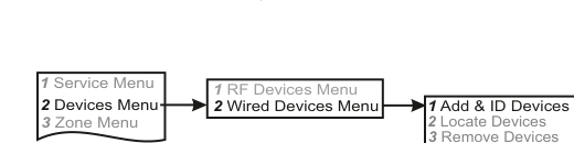
A three-column menu navigation flowchart. First column: 1 Service Menu / 2 Devices Menu / 3 Zone Menu. Arrow leads to second column: 1 RF Devices Menu / 2 Wired Devices Menu. Arrow leads to third column: 1 Add & ID Devices / 2 Locate Devices / 3 Remove Devices.
Menu path: 2 Devices Menu → 2 Wired Devices Menu → 1 Add & ID Devices
Status LED
The Status LED on the Point ID Sensor will only be illuminated during engineer mode. The following status will be indicated:
| Condition | LED Behaviour |
|---|---|
| No comms to sensor but power is ok | LED ON Steady |
| Not Identified | LED turns off every 4 seconds for half a second |
| Sensor Identified | LED Turns on for half a second every 4 seconds |
| Sensor located | LED turns on and off every second |