SW-10270 Panel / Power Supply Unit
You can convert some of your hardwired zones (zones 5, 6, 7 & 8) into Point ID buses. This allows you to wire-in a maximum of five Power Supplies per ID bus (i.e. twenty in total)
- Wire-up zone (see wiring example below).
- In engineer mode, scroll to the Zone Menu. Press YES and scroll to Zone Hardware. Press YES again. Scroll down to the zone you are interested in (e.g. in the wiring examples below you would select zone 5 and 6).
- Scroll to Point ID. Then press YES. The system will automatically check the data bus for all Output Cards. When the scanning finishes, quit from this branch of the menu....
Zone Hardware Menu
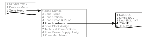
A three-column menu navigation flowchart. First column: 1 Service Menu / 2 Devices Menu / 3 Zone Menu (highlighted). Arrow leads to second column: 1 Zone Names / 2 Zone Types / 3 Zone Options / 4 Zone Gross & Pulse / 5 Zone Hardware (highlighted) / 6 Zone Block Assign / 7 Technical Zone Options / 8 Zone Power Supply Assign / 9 Zone Map Menu. Arrow from 5 Zone Hardware leads to third column: 1 Non EOL / 2 Single EOL / 3 Dual EOL 4K7 / 4 Point ID (highlighted) / 5 RF Device.
Menu path: 3 Zone Menu → 5 Zone Hardware → 4 Point ID
Wiring Diagram
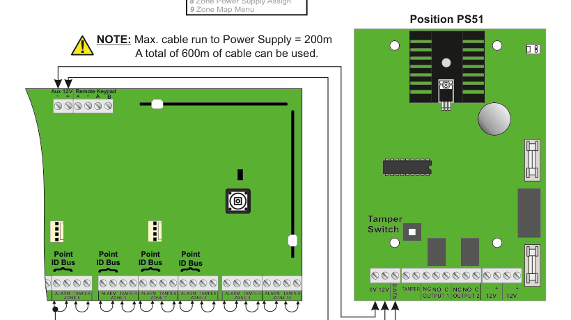
A wiring diagram showing the SW-10270 panel (green PCB, left) connected to a Power Supply Unit (right) via Point ID data buses. The panel shows connections for Aux 12V, Remote Keypad (A, B), and four Point ID Bus connectors at the bottom corresponding to zones 5 through 8. The zone terminal strip at the bottom of the panel shows paired ALARM and TAMPER terminals for ZONE 5, ZONE 6, ZONE 7, ZONE 8, ZONE 9, and ZONE 10. The DATA line from the panel connects to the PSU. A warning note states: "Max. cable run to Power Supply = 200m. A total of 600m of cable can be used."
Max. cable run to Power Supply = 200m. A total of 600m of cable can be used.
Please ensure that zone terminals are linked as shown.
PSU Board Detail (Position PS51)
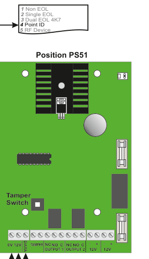
A detailed view of the Power Supply Unit board labelled Position PS51. The green PCB shows a Tamper Switch on the left side. The terminal strip along the bottom edge has the following connections from left to right: 0V, 12V, DATA, TAMPER, NC / NO / C (OUTPUT 1), NC / NO / C (OUTPUT 2), + / 12V, + / 12V.
PSU Terminal Connections
| Terminal | Description |
|---|---|
| 0V | Ground (0V) |
| 12V | 12V supply |
| DATA | Data bus connection to panel zone |
| TAMPER | Tamper switch connection |
| NC (OUTPUT 1) | Normally Closed — Output 1 relay |
| NO (OUTPUT 1) | Normally Open — Output 1 relay |
| C (OUTPUT 1) | Common — Output 1 relay |
| NC (OUTPUT 2) | Normally Closed — Output 2 relay |
| NO (OUTPUT 2) | Normally Open — Output 2 relay |
| C (OUTPUT 2) | Common — Output 2 relay |
| + / 12V | Auxiliary 12V output |
Example: Adding a Power Supply in position 51
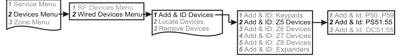
A five-column menu navigation flowchart. First column: 1 Service Menu / 2 Devices Menu (highlighted) / 3 Zone Menu. Arrow leads to second column: 1 RF Devices Menu / 2 Wired Devices Menu (highlighted). Arrow leads to third column: 1 Add & ID Devices (highlighted) / 2 Locate Devices / 3 Remove Devices. Arrow leads to fourth column: 1 Add & ID: Keypads / 2 Add & ID: Z5 Devices (highlighted) / 3 Add & ID: Z6 Devices / 4 Add & ID: Z7 Devices / 5 Add & ID: Z8 Devices / 6 Add & ID: Expanders. Arrow leads to fifth column: 1 Add & Id: P50..P59 / 2 Add & Id: PS51.55 (highlighted) / 3 Add & Id: OC51.55.
Menu path: 2 Devices Menu → 2 Wired Devices Menu → 1 Add & ID Devices → 2 Add & ID: Z5 Devices → 2 Add & Id: PS51.55
- Go to Devices Menu and select YES. Scroll to Wired Devices Menu and press YES. Then select Add & Id Devices.
- Add & Id:Keypads will be on the display. Scroll to Add & Id:Z5 Devs. This is shorthand for: Add and identify devices on zone 5's data bus.
- Press YES.
- Add & Id:P50..59 will be on the display. Scroll to Add & Id:PS51.55. This is shorthand for: Add and identify any power supply on zone 5's data bus and name them Power Supply 51, Power Supply 52 etc.
- Press YES.
- When prompted, close the tamper switch on the Power Supply. The 1st Power Supply has now been added to the system in location PS51. The system is now ready to accept the 2nd Power Supply in location PS52 and so on.
Example: Programming output number 1 on output card PS51
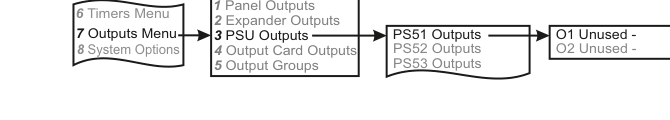
A four-column menu navigation flowchart. First column: 6 Timers Menu / 7 Outputs Menu (highlighted) / 8 System Options. Arrow leads to second column: 1 Panel Outputs / 2 Expander Outputs / 3 PSU Outputs (highlighted) / 4 Output Card Outputs / 5 Output Groups. Arrow leads to third column: PS51 Outputs (highlighted) / PS52 Outputs / PS53 Outputs. Arrow leads to fourth column: O1 Unused - / O2 Unused -.
Menu path: 7 Outputs Menu → 3 PSU Outputs → PS51 Outputs → O1 Unused -
- Go to Outputs Menu and select YES. Scroll to Psu Outputs and press YES. Psu is shorthand for Power Supply Unit.
- PS51 Outputs will be on the display. Press YES or scroll to power supply numbers and then press YES.
- You should see O1 Unused - on the display. Press YES or scroll to other individual output numbers on the unit in question and then press YES. You can now select an output type from the list on page 75.
- Once you have selected your output type you will be prompted to select between negative or positive polarity.
Example: Locating Power Supply in position 51
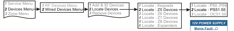
A five-column menu navigation flowchart. First column: 1 Service Menu / 2 Devices Menu (highlighted) / 3 Zone Menu. Arrow leads to second column: 1 RF Devices Menu / 2 Wired Devices Menu (highlighted). Arrow leads to third column: 1 Add & ID Devices / 2 Locate Devices (highlighted) / 3 Remove Devices. Arrow leads to fourth column: 1 Locate : Keypads / 2 Locate : Z5 Devices (highlighted) / 3 Locate : Z6 Devices / 4 Locate : Z7 Devices / 5 Locate : Z8 Devices / 6 Locate : Expanders. Arrow leads to fifth column: 1 Locate : P50..P59 / 2 Locate : PS51.55 (highlighted) / 3 Locate : OC51.55.
Menu path: 2 Devices Menu → 2 Wired Devices Menu → 2 Locate Devices → 2 Locate : Z5 Devices → 2 Locate : PS51.55
- Go to Devices Menu and select YES. Scroll to Wired Devices Menu and press YES. Then select Locate Devices.
- Locate:Keypads will be on the display. Scroll to Locate:Z5 Devs. Press YES.
- Locate:P50..59 will be on the display. Scroll to Locate:PS51.55. Press YES.
- PS51 PSUNumber51 will be on the display and the Fault LED on the front of Power Supply 51 will be flashing on and off every second. Pressing NEXT brings to Power Supply 52 and so on.
12V Power Supply Front Panel
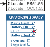
A front panel view of the 12V Power Supply showing four LED indicators: Mains Fault, Battery OK, Fault, and Battery Test. Below the LEDs are two rating options: 1 Amp total and 2 Amp total.
| Indicator | Description |
|---|---|
| Mains Fault | LED indicates mains power failure |
| Battery OK | LED indicates battery status is OK |
| Fault | LED indicates a fault condition |
| Battery Test | LED indicates battery test in progress |
| Rating | Description |
|---|---|
| 1 Amp total | 1 Amp total power supply variant |
| 2 Amp total | 2 Amp total power supply variant |