SW-10270 Panel / 10-Zone Expander
Wiring Diagram
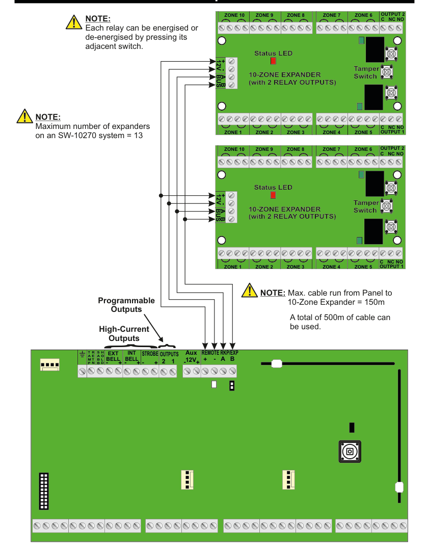
A wiring diagram showing an SW-10270 panel connected to two 10-Zone Expanders via the REMOTE RKP/EXP terminals on the panel (+, -, A, B). Four bus wires (12V +, -, BUS A, BUS B) run from the panel to each expander in a daisy-chain configuration. Top expander: A green PCB labelled 10-ZONE EXPANDER (with 2 RELAY OUTPUTS), showing a Status LED (top-centre), a Tamper Switch (right side), zone terminals along the bottom edge ZONE 1, ZONE 2, ZONE 3, ZONE 4, ZONE 9 and along the top edge ZONE 10, ZONE 5, ZONE 8, ZONE 7, ZONE 6, relay outputs OUTPUT 1 (bottom-right, with C, NC, NO terminals) and OUTPUT 2 (top-right, with C, NC, NO terminals), and bus terminals 12V, +, -, A, B (top-left). Bottom expander: Identical layout. The panel terminal strip (bottom of diagram) shows, left to right: earth, TAMP, RETN, SABB, HOLD, EXT BELL, INT BELL, STROBE, OUTPUTS 2 1, Aux 12V +, REMOTE RKP/EXP + - A B. Arrows indicate Programmable Outputs and High-Current Outputs on the panel.
Each relay can be energised or de-energised by pressing its adjacent switch.
Maximum number of expanders on an SW-10270 system = 13
Max. cable run from Panel to 10-Zone Expander = 150m
A total of 500m of cable can be used.
Adding a 10-Zone Expander
Example: Adding a 10-Zone Expander in position Exp1.
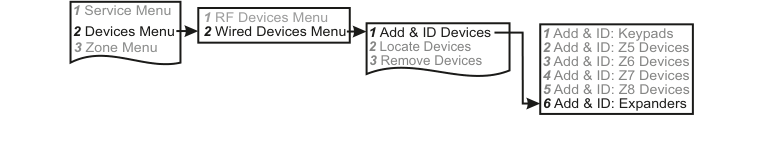
A four-column menu navigation flowchart. First column: 1 Service Menu / 2 Devices Menu (highlighted) / 3 Zone Menu. Arrow leads to second column: 1 RF Devices Menu / 2 Wired Devices Menu (highlighted). Arrow leads to third column: 1 Add & ID Devices (highlighted) / 2 Locate Devices / 3 Remove Devices. Arrow leads to fourth column: 1 Add & ID: Keypads / 2 Add & ID: Z5 Devices / 3 Add & ID: Z6 Devices / 4 Add & ID: Z7 Devices / 5 Add & ID: Z8 Devices / 6 Add & ID: Expanders (highlighted).
- Go to Devices Menu and select YES. Scroll to Wired Devices Menu and press YES. Then select Add & Id Devices.
- Add & Id:Keypads will be on the display. Scroll to Add & Id:Expandr and press YES.
- Scanning Expandr will be on the display. When prompted, close the tamper switch on the 10-Zone Expander.
The 1st 10-Zone Expander has now been added to the system in location Exp1. The system is now ready to accept the 2nd 10-Zone Expander in location Exp2 and so on.
Programming the Outputs
Example: Programming the outputs on the 10-Zone Expander Exp1.
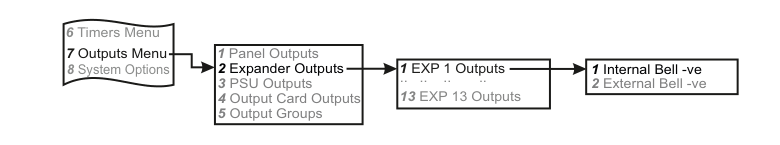
A four-column menu navigation flowchart. First column: 6 Timers Menu / 7 Outputs Menu (highlighted) / 8 System Options. Arrow leads to second column: 1 Panel Outputs / 2 Expander Outputs (highlighted) / 3 PSU Outputs / 4 Output Card Outputs / 5 Output Groups. Arrow leads to third column: 1 EXP 1 Outputs (highlighted) / .. .. .. .. / 13 EXP 13 Outputs. Arrow leads to fourth column: 1 Internal Bell -ve / 2 External Bell -ve.
- Go to Outputs Menu and select YES.
- Scroll to Expander Outputs and press YES.
- You should see EXP1 Outputs on the display. Press YES or scroll to another expander.
- 01 Int. Bell - will be on the display. Either press YES or scroll to 02 Ext. Bell - and press YES.
- You can now select an output type from the list on page 75.
- Once you have selected your output type you will be prompted to select between negative or positive polarity.
Locating the Expander
Example: Locating the 10-Zone Expander Exp1 & Exp2.
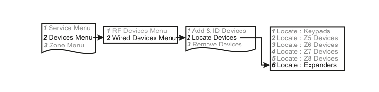
A four-column menu navigation flowchart. First column: 1 Service Menu / 2 Devices Menu (highlighted) / 3 Zone Menu. Arrow leads to second column: 1 RF Devices Menu / 2 Wired Devices Menu (highlighted). Arrow leads to third column: 1 Add & ID Devices / 2 Locate Devices (highlighted) / 3 Remove Devices. Arrow leads to fourth column: 1 Locate : Keypads / 2 Locate : Z5 Devices / 3 Locate : Z6 Devices / 4 Locate : Z7 Devices / 5 Locate : Z8 Devices / 6 Locate : Expanders (highlighted).
- Go to Devices Menu and select YES. Scroll to Wired Devices Menu and press YES. Then select Locate Devices.
- Press YES. Locate :Keypads will be on the display. Scroll to Locate : Expanders and Press YES.
- After a short while Exp1 Exp1 will be on the display and the status LED 10-Zone Expander number 1will be flashing on and off every second.
- Pressing NEXT will bring you on to Exp2 Exp2. Now the status LED on the 10-Zone Expander number 2 will start flashing on and off every second.