System Hardware: Main Panel
Red LED for internal purposes only.
SW-1070 Main Panel Circuit Board Layout
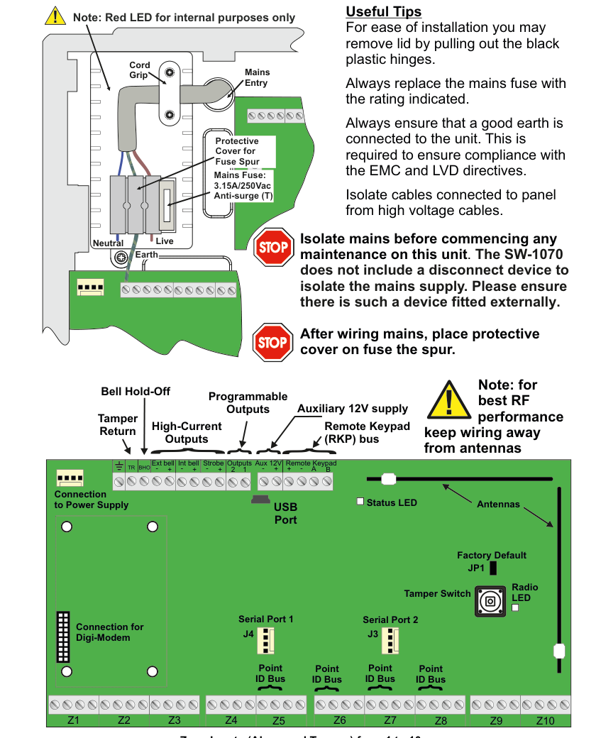
The SW-1070 main panel circuit board layout diagram viewed from above. The board is shown as a green PCB inside a grey enclosure, with the following labeled components organized by region:
Top terminal strip (left to right):
- EXT BELL — External bell output with four vertically-labeled sub-terminals: TAMP (Tamper), SABB (Self-Activating Bell Box), RETN (Return), HOLD (Hold-Off).
- INT BELL — Internal bell output (+ and - terminals).
- STROBE — Strobe output (+ and - terminals).
- OUTPUTS — Programmable outputs with terminals labeled +, 2, 1.
- Aux 12V — Auxiliary 12V supply with + and - terminals.
- REMOTE RKP/EXP — Remote Keypad / Expander bus with terminals labeled +, -, A, B.
Left-side callout labels (top to bottom, describing the top terminal strip groupings):
- Bell Hold-Off — refers to the HOLD terminal on the EXT BELL group.
- High-Current Outputs — refers to the EXT BELL, INT BELL, and STROBE outputs.
- Tamper Return — refers to the TAMP and RETN terminals on the EXT BELL group.
- Programmable Outputs — refers to the OUTPUTS terminals (+ 2 1).
- Auxiliary 12V supply — refers to the Aux 12V (+ -) terminals.
- Remote Keypad (RKP) bus — refers to the REMOTE RKP/EXP (+ - A B) terminals.
Left side (zone inputs):
- Z1 through Z10 — Zone inputs arranged vertically along the left edge of the board. Each zone has two pairs of terminals: Alarm and Tamper. Zones are numbered 1 to 10 from top to bottom. A label at the bottom reads: "Zone Inputs (Alarm and Tamper) from 1 to 10."
Centre-left (connectors, top to bottom):
- Serial Port 1 — First serial port connector.
- Point ID Bus (x4) — Four Point ID Bus connection headers arranged vertically.
- Connection to Power Supply — Connector for the panel's power supply unit.
- Connection for Digi-Modem — Connector for the digital modem module.
Centre-right and right side (top to bottom):
- Z8, Z9, Z10 — Additional zone input labels on the right side of the zone input area.
- Antennas — Two RF antennas located in the upper-right area of the board with a note: "for best RF performance keep wiring away from antennas."
- Tamper Switch — Board tamper switch.
- Status LED — Status indicator LED.
- Radio LED — Radio activity indicator LED.
- Factory Default — Factory default reset button/jumper.
- Serial Port 2 — Second serial port connector.
- JP1 — Jumper JP1.
- J3 — Connector J3.
- J4 — Connector J4.
- USB Port — USB port connector located at the bottom-right of the board.
Right side (Mains Entry area, outside the board in the enclosure):
- Mains Entry label with: Live, Neutral, Earth connections.
- Cord Grip — Cable strain relief.
- Mains Fuse: 3.15A/250Vac Anti-surge (T) — Mains fuse rating.
- Protective Cover for Fuse Spur — Protective cover over the fuse spur area.
Safety warnings (right side, marked with yellow hazard triangle symbols):
- Warning 1: "Isolate mains before commencing any maintenance on this unit. The SW-1070 does not include a disconnect device to isolate the mains supply. Please ensure there is such a device fitted externally."
- Warning 2: "After wiring mains, place protective cover on fuse the spur."
Top Terminal Strip
The top edge of the main panel board contains the following terminal groups, from left to right:
| Terminal Group | Terminals | Description |
|---|---|---|
| EXT BELL | TAMP, SABB, RETN, HOLD | External bell output with Tamper, Self-Activating Bell Box, Return, and Hold-Off sub-terminals |
| INT BELL | +, - | Internal bell output (high-current) |
| STROBE | +, - | Strobe output (high-current) |
| OUTPUTS | +, 2, 1 | Programmable outputs |
| Aux 12V | +, - | Auxiliary 12V DC supply |
| REMOTE RKP/EXP | +, -, A, B | Remote Keypad / Expander data bus |
Zone Inputs
Zones Z1 through Z10 are arranged vertically along the left side of the board. Each zone provides both Alarm and Tamper terminal pairs, numbered 1 to 10.
Serial Ports and Data Connections
| Component | Description |
|---|---|
| Serial Port 1 | First serial port connector (centre-left of board) |
| Serial Port 2 | Second serial port connector (right side of board) |
| Point ID Bus (x4) | Four Point ID Bus connection headers for wired point-ID sensors |
| Connection to Power Supply | Connector linking to the panel PSU |
| Connection for Digi-Modem | Connector for the optional digital modem module |
| USB Port | USB port (bottom-right of board) |
Other On-Board Components
| Component | Description |
|---|---|
| Antennas | Two RF antennas (upper-right area) |
| Tamper Switch | Board tamper detection switch |
| Status LED | System status indicator |
| Radio LED | RF radio activity indicator |
| Factory Default | Factory default reset |
| JP1 | Jumper JP1 |
| J3 | Connector J3 |
| J4 | Connector J4 |
For best RF performance keep wiring away from antennas.
Useful Tips
- For ease of installation you may remove lid by pulling out the black plastic hinges.
- Always replace the mains fuse with the rating indicated.
- Always ensure that a good earth is connected to the unit. This is required to ensure compliance with the EMC and LVD directives.
- Isolate cables connected to panel from high voltage cables.
Mains Entry
The mains entry area is located on the right side of the enclosure, outside the main circuit board.
| Component | Details |
|---|---|
| Live | Mains live connection |
| Neutral | Mains neutral connection |
| Earth | Mains earth connection |
| Cord Grip | Cable strain relief for mains cable entry |
| Mains Fuse | 3.15A / 250Vac Anti-surge (T) |
| Protective Cover for Fuse Spur | Cover to protect the fuse spur after wiring |
Safety Warnings
Isolate mains before commencing any maintenance on this unit. The SW-1070 does not include a disconnect device to isolate the mains supply. Please ensure there is such a device fitted externally.
After wiring mains, place protective cover on fuse the spur.